
Pneumatic tire

a pneumatic tire and tire body technology, applied in the field of pneumatic tires, can solve the problems of deteriorating ride comfort, over-breaking the breaking limits of the side reinforcing layer and the bead filler, and affecting the smoothness of the ride, so as to improve the rolling resistance and improve the ride comfor

Inactive Publication Date: 2011-12-01
BRIDGESTONE CORP
View PDF6 Cites 18 Cited by
  • Summary
  • Abstract
  • Description
  • Claims
  • Application Information

AI Technical Summary

Benefits of technology

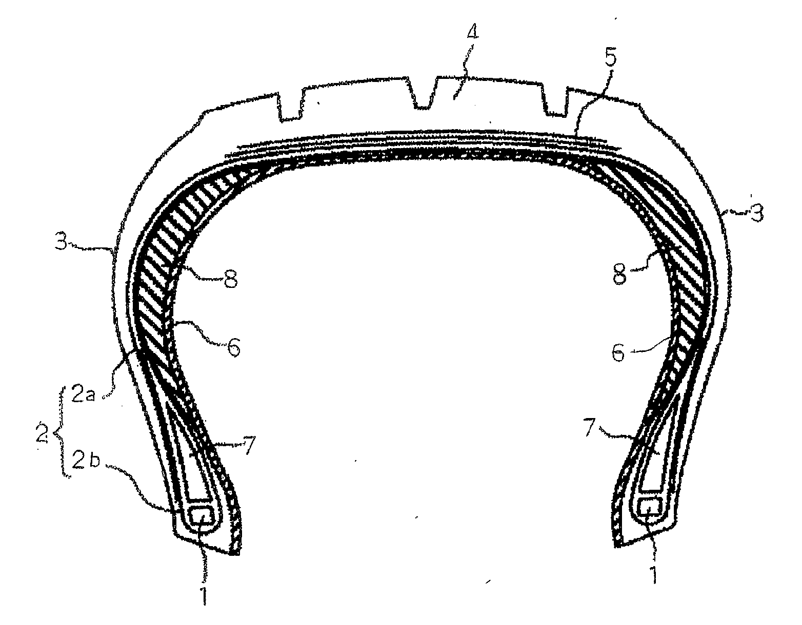
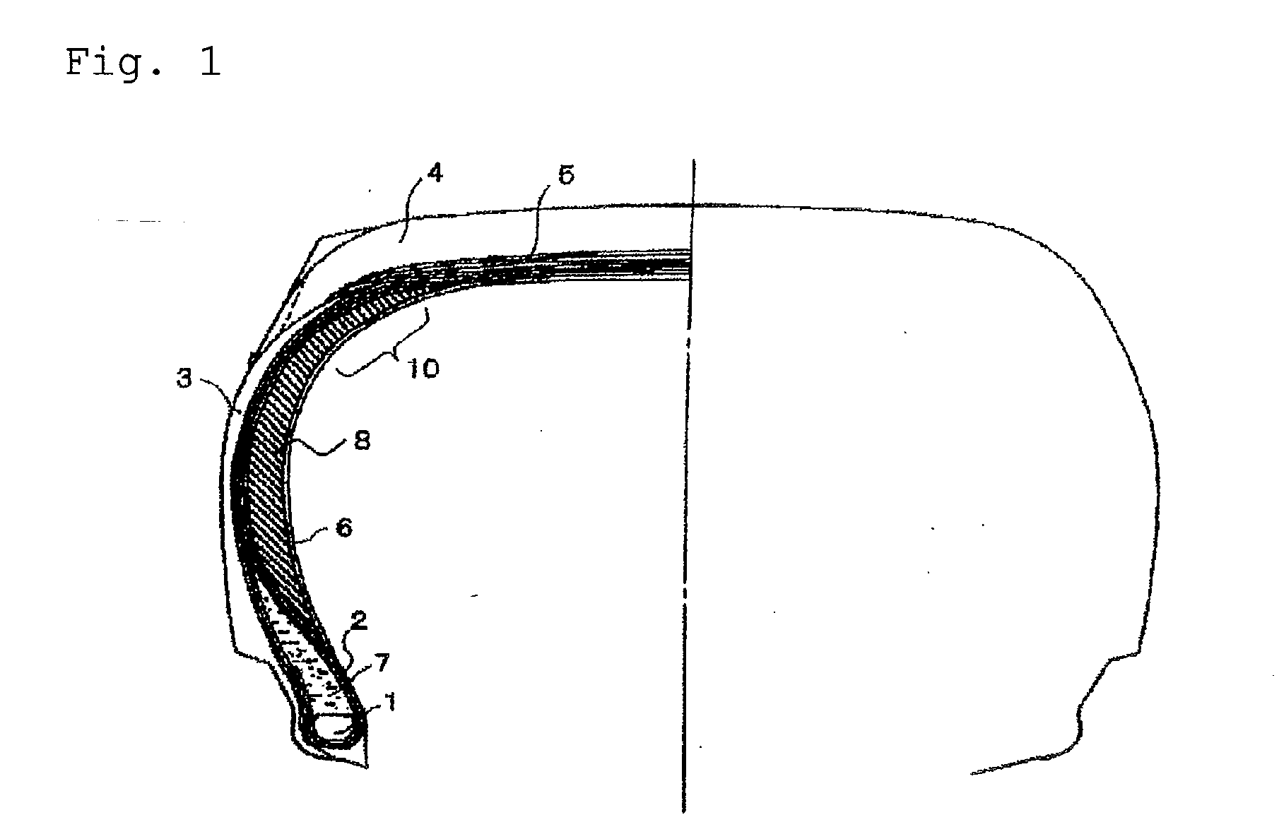
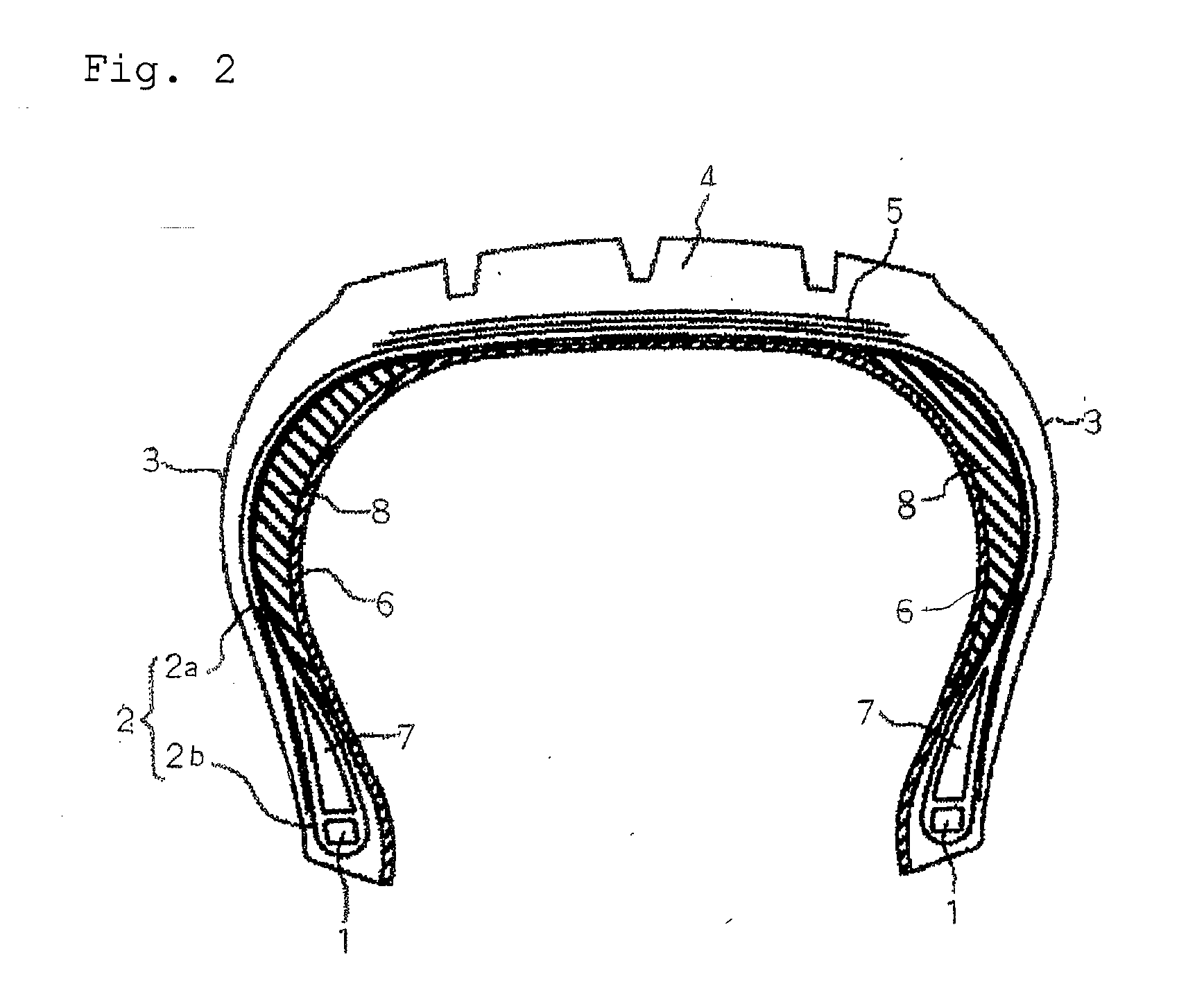
[0017]Under the situation described above, an object of the present invention is to provide a pneumatic tire which is improved in a rolling resistance and a ride comfort in normal running without damaging a run flat durability.
[0020]According to the present invention,(1) a dynamic storage modulus (E′) at a dynamic strain of 1% and 25° C. is controlled to 1 to 10 MPa, preferably 3 to 10 MPa and more preferably 3 to 8 MPa in the vulcanized rubber physical properties by reducing (preferably 50 parts by mass or less) a content of the filler (particularly carbon black) contained in the rubber composition, whereby the side rigidity can be softened to enhance the ride comfort in normal running.
[0022]As described above, according to the effects of (1) to (5), using the rubber composition (a) particularly for the side reinforcing rubber layer and / or the bead filler and using the rubber composition (b) for the inner liner make it possible to provide a pneumatic tire in which a side reinforcing rubber layer is inhibited from being peeled off from an inner liner while maintaining an air non-permeability of the inner liner to enhance a run flat durability thereof and in which a rolling resistance and a ride comfort in normal running are improved.

Problems solved by technology

In the above state, even a pneumatic tire provided with a side reinforcing layer exceeds the breaking limits of the side reinforcing layer and the bead filler and comes to have troubles.
However, the problem that the tire is elevated in a rolling resistance in normal running and reduced in a low fuel consumption is involved therein.
All of them have a purpose of enhancing an elastic modulus of the rubber compositions used for a side reinforcing layer and a bead filler and inhibiting a reduction in the elastic modulus at high temperatures, and an improvement in the run flat resistance to large extent is obtained, but the rolling resistance in normal running is notably deteriorated.
On the other hand, means for extending time spent until the troubles described above are caused include increasing a volume of the rubber such as increasing a maximum thickness of a mounted side reinforcing layer and a mounted bead filler, but when the above method is employed, unfavorable situations such as deterioration of the ride comfort in normal running, an increase in the weight and an increase in the noise level are brought about.
If a mounted side reinforcing layer and a mounted bead filler are reduced in a volume in order to avoid the situations described above, for example, deterioration of the ride comfort, the problems that a load in run flat can not be supported to deform a side wall part of the tire to a large extent in run flat and that an increase in heat of the rubber composition is brought about to result in allowing the tire to come to cause troubles earlier have been involved therein.
Further, when the rubber used is reduced in an elasticity by changing the materials blended, it is the existing situation that a load in run flat can not be supported as well to deform a side wall part of the tire to a large extent and that an increase in heat of the rubber composition is brought about to result in allowing the tire to come to cause troubles earlier.
As a result thereof, the side reinforcing rubber layer is readily peeled off from the inner liner in running in a state in which the tire is reduced in an inner pressure by blowout and the like (hereinafter referred to as run flat running), and a problem has been involved in the run flat durability.

Method used


Image

  • Pneumatic tire
  • Pneumatic tire
  • Pneumatic tire

Examples


production example 1

Primary Amine-Modified Polybutadiene

(1) Production of Polybutadiene

[0147]A 5 L autoclave substituted with nitrogen was charged with 1.4 kg of cyclohexane, 250 g of 1,3-butadiene and 2,2-ditetrahydrofurylpropane (0.0285 mmol) in the form of a cyclohexane solution under nitrogen flow, and after 2.85 mmol of n-butyllithium (BuLi) was added thereto, polymerization was carried out for 4.5 hours in a warm water bath of 50° C. equipped with a stirring device. A reaction conversion rate of 1,3-butadiene was almost 100%. The above polymer solution was put in a methanol solution containing 1.3 g of 2,6-di-tert-butyl-p-cresol to terminate the polymerization, and then the solvent was removed by steam stripping. The resulting solid matter was dried on a roll of 110° C. to obtain polybutadiene. The polybutadiene thus obtained was used to measure a micro structure (vinyl bonding amount), a weight average molecular weight (Mw) and a molecular weight distribution (Mw / Mn). The results thereof showed ...

production example 2

Production of Secondary Amine-Modified Polybutadiene

[0149]N-methyl-N-(trimethylsilyl)aminopropylmethyldiethoxy-silane which was secondary amine was used as the modifying agent to carry out modification reaction based on (2) described above, and secondary amine-modified polybutadiene was obtained.

production example 3

Production of Tertiary Amine-Modified Polybutadiene

[0150]DMAPES: 3-dimethylaminopropyl(diethoxy)methylsilane was used as the modifying agent to carry out modification reaction based on (2) described above, and tertiary amine-modified polybutadiene was obtained.


PUM

PropertyMeasurementUnit
loss tangent tan δaaaaaaaaaa
dynamic storage modulusaaaaaaaaaa
aspect ratioaaaaaaaaaa

Abstract

Provided is a pneumatic tire which is improved in a rolling resistance and a ride comfort in normal running without damaging a run flat durability.It is a pneumatic tire provided with a bead core, a carcass layer, a tread rubber layer, an inner liner, a side reinforcing layer and a bead filler, characterized by using a rubber composition (a) which contains (A) a rubber component and (B) a filler and which has a dynamic storage modulus (E′) of 10 MPa or less at a dynamic strain of 1% and 25° C. and a Σ value of 5.0 or less in a loss tangent tan δ at 28 to 150° C. in the physical properties of the vulcanized rubber.

Description

BACKGROUND OF THE INVENTION[0001]The present invention relates to a pneumatic tire improved in a rolling resistance and a ride comfort in normal running without damaging a run flat durability, wherein a rubber composition having a dynamic storage modulus (E′) of a certain value or less and a Σ value of a certain value or less in a loss tangent tan δ at 28 to 150° C. in the characteristics of the vulcanized rubber is used particularly for a side reinforcing layer and / or a bead filler, and a rubber composition in which an air permeability coefficient at 60° C. is a certain value or lower is used for an inner liner.RELATED ART[0002]Run flat tires of a side reinforcing type in which a cross-sectionally lunate side reinforcing rubber layer is disposed at an innermost side of a carcass in a side wall part of the tire to enhance a rigidity of the side wall part have so far been known as a tire capable of running safely in a distance of a certain extent even in a state in which an inner pre...

Claims


Application Information

Patent Timeline
Patent Type & Authority Applications(United States)
IPC IPC(8): B60C5/00
CPCB60C1/00Y10T152/10495B60C5/14C08C19/44C08K3/0033C08K3/04C08L15/00B60C1/0008B60C17/0009B60C2017/0063B60C2001/0033C08L7/00C08K3/013Y02T10/86
Inventor NAKAGAWA, RYUJIKANO, HORIHISA
Owner BRIDGESTONE CORP
Learn More