Single-stage AC-to-DC converter with isolation and power factor correction

a single-stage ac-to-dc converter and isolation technology, applied in the field of acdc conversion, can solve the problems of low efficiency, large size and weight, high cost, etc., and achieve the effect of reducing size, reducing cost and increasing efficiency simultaneously

Inactive Publication Date: 2011-12-01
CUKS
View PDF6 Cites 71 Cited by
  • Summary
  • Abstract
  • Description
  • Claims
  • Application Information

AI Technical Summary

Benefits of technology

The prior-art solutions which provide the PFC function and isolation do so by use of the multiple power conversion stages connected in series (typically three), thus degrading efficiency and increasing cost and size. To realize PFC and isolation features, the prior art sue as a first stage full bridge rectifier, a separate non-isolated switching DC-DC converter to provide the PFC function and low total harmonic distortion of the input AC current. Since the present DC-DC converters used for PFC (for example, the non-isolated boost converter) have no isolation, the third DC-DC converter power processing stage with isolation transformer is needed (for example, phase-shifted full-bridge converter for high power or forward converter for medium to low power). It is clear that the present AC-to-DC solutions then require three cascaded converters (bridge rectifier followed by two DC / DC converters) so that total power is processed three times resulting in low overall efficiency and high power losses. Until this invention, it was considered impossible to have a Direct AC-DC converter with PFC and isolation features provided in a single power processing stage and without full-bridge rectifier. The present invention dispels that widely held belief by providing a single-stage AC-to-DC switching converter with built-in (inherent) PFC and isolation features, so that the present inefficient and costly three-stage power processing solutions could be replaced.

Problems solved by technology

The present solutions can provide these functions but to do so they use predominantly three power processing stages, which result in low efficiency, big size and weight and high cost.
The alternative present solutions employing two power-processing stages result even in lower efficiency and bigger size.
The prior-art simple AC-DC converter comprising of only full bridge rectifier followed by the large capacitor is not allowed as a single-stage solution due to injection of the high frequency harmonics into utility line.
The prior-art solutions which provide the PFC function and isolation do so by use of the multiple power conversion stages connected in series (typically three), thus degrading efficiency and increasing cost and size.
It is clear that the present AC-to-DC solutions then require three cascaded converters (bridge rectifier followed by two DC / DC converters) so that total power is processed three times resulting in low overall efficiency and high power losses.
By judicious design of Integrated Magnetics, the high switching frequency ripple is shifted to isolation transformer from the input inductor L to result in noise-free input AC line current.
This narrow and distorted input current pulse has two fundamental drawbacks:a) a lot of high frequency current harmonics are generated and injected into the AC line side, which are not in compliance with requirements defined by the IEC 1000-3-2 harmonic currents standard.b) a very low power factor is present, which significantly reduces the available real power from the utility line since the large reactive current generates high peak circulating and corresponding losses in transmission lines without delivering any power to the load.
There are no single-stage prior art solutions.
This solution is clearly undesirable as it consists of three cascaded power-processing stages: full-bridge rectifier, PFC boost converter and isolated DC-DC converter each of which simultaneously decreases the efficiency, increases the size and increases the cost.
The corresponding two-diode voltage drops at low AC line voltage of 85 VAC result in additional 3% losses.
However, they all failed to achieve the desirable goal of eliminating input bridge as they operate only from the positive polarity of the input voltage.
Therefore, prior-art alternatives could not accomplish the bridgeless PFC operation by using existing DC-DC converter structures due to their inability to accept the input voltage of either polarity (positive or negative) and yet generate the output voltage of only one polarity, such as positive.
Although the claims are made that it is a bridgeless converter, this is easily seen to be false, as the two low frequency diode rectifiers D3 and D4 of the four diodes in full-bridge rectifiers are still retained causing aforementioned losses.
Therefore, in addition to the reduced efficiency due to additional diode drops (only half of the diodes in the full-bridge are eliminated), it also suffers from doubling the number of components and cost in comparison to the previous prior-art single boost PFC converter.
Thus, the components in double-boost converter of FIG. 7a are poorly utilized as they are used only half of the time resulting in serious penalty in weight, size and cost, while only marginally improving efficiency by eliminating one diode voltage drop for each half cycle.

Method used


Image

  • Single-stage AC-to-DC converter with isolation and power factor correction
  • Single-stage AC-to-DC converter with isolation and power factor correction
  • Single-stage AC-to-DC converter with isolation and power factor correction

Examples


##s embodiment

Integrated Magnetics Embodiment

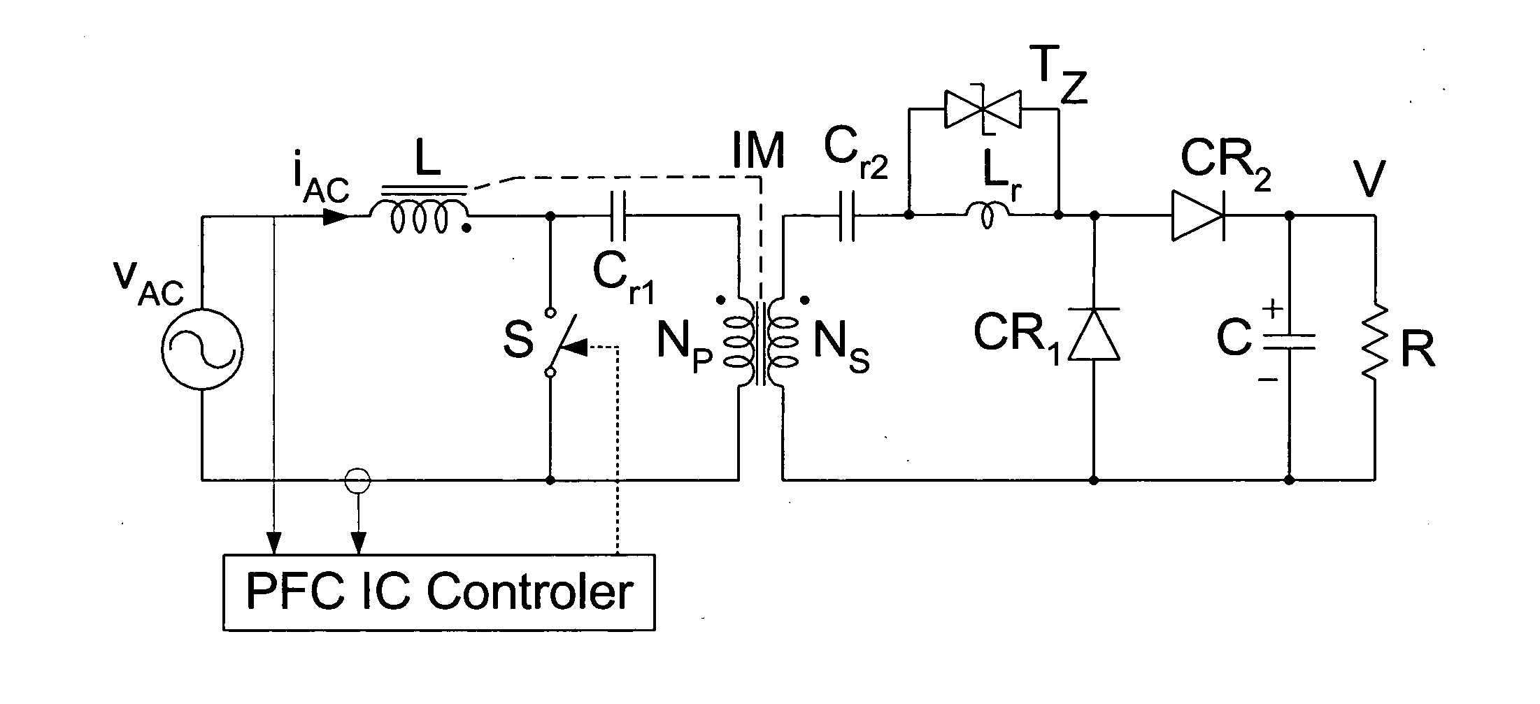
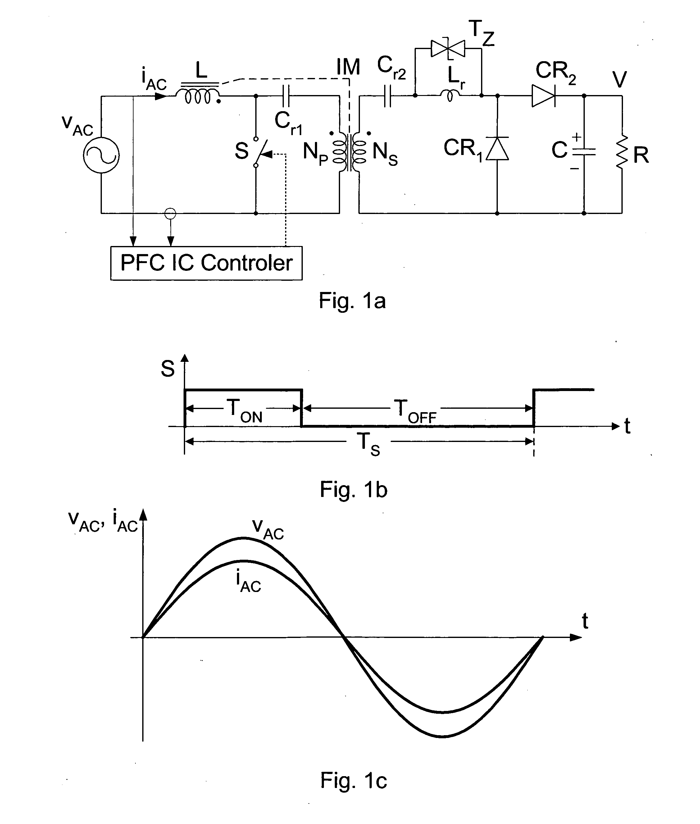
The voltage waveforms of the inductor L and transformer T in the converter of FIG. 1a are identical as seen in FIG. 39a. This then makes it possible to integrate the inductor and transformer on the common core to result in the integrated magnetics (IM) structure of FIG. 39b which in turn, by judicious design of the magnetics, will result in the removal of the input ripple current, or actually its shift into the transformer windings so that the high frequency ripple current is eliminated and the need for separate high frequency filter is also eliminated. Yet the smooth noise free input current of FIG. 1c is obtained.

Shown in FIG. 40a-c is the case of another possible modulation strategy, that is constant OFF-time and variable ON time modulation.

Converter Start-up

The DC gain characteristic of (4) suggests that the isolated converter would have the start-up problem as the DC gain characteristic is always greater than 1. Yet at start-up the output DC volta...

experimental verifications

The Single-Stage AC-DC Converter with Isolation and Power factor Correction (PFC) performance features is verified by on an experimental 400 W prototype, which converts 110V AC line voltage and 220V AC line voltage into a 400V isolated output voltage with very high efficiency over the wide range. FIG. 42a shows the efficiency measurements at a 300 W level over the wide input AC voltage range from 85V AC to 240V AC and FIG. 42b shows the corresponding FIG. 43a shows the line voltage (top trace) and AC line current (bottom trace). The Power factor was measured at 300 W load to be 0.999. loss measurements.

Very high efficiency of over 97% was measured over the wide input AC voltage. In particular note the very high efficiency at the low AC line voltage of 85VAC as shown in FIG. 42a while the low total losses are shown in FIG. 42bb. This clearly indicates the absence of the bridge rectifier on the front. The prior-art PFC converters have a significant efficiency drop at the low 85V AC li...


PUM


Abstract

A new class of Single-Stage AC-DC converters with built-in Isolation and PFC feature is introduced along with the companion hybrid switching conversion method. Several different converter topologies are introduced, which all feature three switches only, single magnetic component and low voltage stresses on all switches.

Description

FIELD OF INVENTIONThis invention relates to the field of AC-DC conversion, which can provide the galvanic isolation and Power Factor Correction performance features. The present solutions can provide these functions but to do so they use predominantly three power processing stages, which result in low efficiency, big size and weight and high cost. The alternative present solutions employing two power-processing stages result even in lower efficiency and bigger size.The present invention opens up a new class of single-stage AC-DC converters, which provide both galvanic isolation and Power Factor Correction features by processing the AC input power to DC output power in a single power processing stage, thus resulting in much improved efficiency reduced size and weight and lower cost. The new class of single-stage AC-DC converters was made possible by heretofore not available hybrid switching method for step-up conversion, which in turns results in a number of distinct switching conver...

Claims


Application Information

Patent Timeline
Patent Type & Authority Applications(United States)
IPC IPC(8): H02M7/06
CPCY02B70/126H02M1/4258Y02B70/10
Inventor CUK, SLOBODAN
Owner CUKS
Why Eureka
Try Eureka