
Microcapsule for local treatment of a tumor and method for positioning a magnetic gradient field guiding magnetic nanoparticles to a target location as well as apparatus for positioning a magnetic gradient field

Inactive Publication Date: 2011-12-08
SIEMENS AG
View PDF19 Cites 13 Cited by
  • Summary
  • Abstract
  • Description
  • Claims
  • Application Information

AI Technical Summary

Benefits of technology

[0023]The object of the invention is therefore to specify a microcapsule and a positioning method that permit better positioning and improved positioning verification.
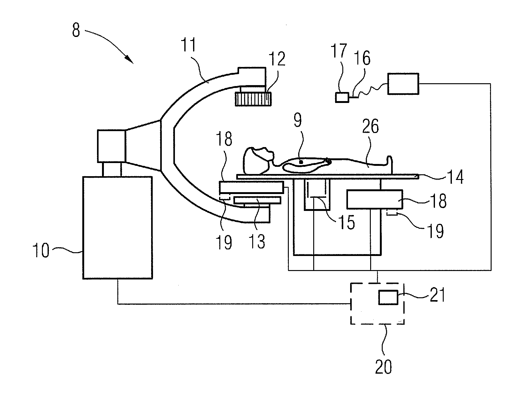
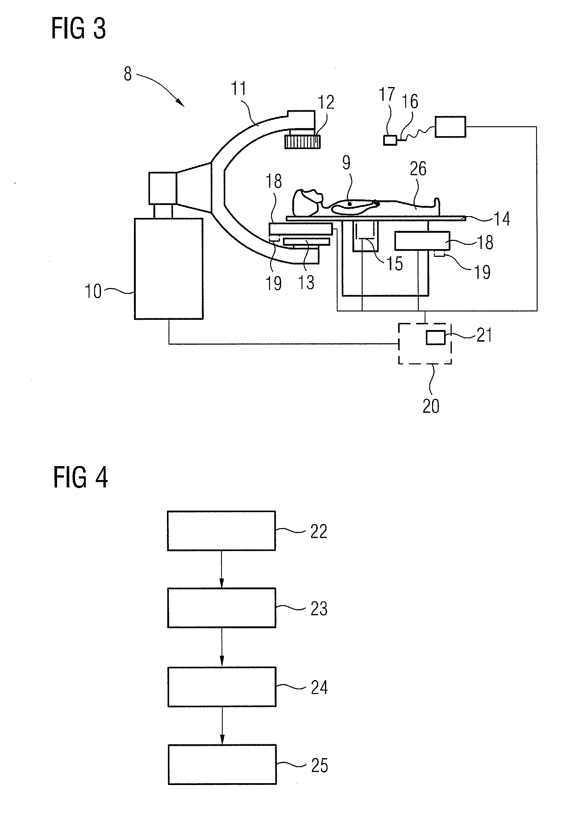
[0037]It is therefore proposed that a catheter with an electromagnetic position sensor, for example one or a number of coils, should be used to decide based on the measured signal how the gradient field or its focal point should be positioned. To this end the catheter is first guided, subject to two-dimensional and / or three-dimensional image monitoring, to the target location, in particular into the tumor volume. The position of the position sensor therefore also corresponds to the position of the target location. The positioning of the gradient field relative to the target location is then changed by relative displacement of the target location with the tumor and the gradient field until the signal from the position sensor indicates that the focal point and the target location correspond. Finally the catheter coordinates are registered with the focal point of the magnetic gradient field. This allows the nanoparticles, and therefore also in particular the microcapsules, to be concentrated locally in an optimum manner at the target location, in particular in the tumor, and tumor cells to be destroyed with minimal side effects on surrounding healthy tissue.
[0043]In a particularly expedient embodiment of the present invention provision can be made for the in particular automatically performed displacement to take place in a directed manner taking account of a magnetic field map describing the gradient field and / or using an optimization method. It can already be known from the design and arrangement of the magnet(s) producing the gradient field, in particular in the form of a magnetic field map, what manner of form and in particular gradient profile the gradient field features, so that it can already be determined or at least qualified from the measurement values of the position sensor, where the catheter and therefore the target location are located relative to the focal point of the gradient field; such information, which can be calculated for example by a control facility, can advantageously be taken into account during displacement, in order to achieve the correspondence of focal point and target location in a quick and simple manner. Alternatively or additionally an optimization method can be employed, which ascertains for example based on short test displacements whether the desired change in the sensor signals is present so that an optimum displacement direction can be determined in order gradually to reach the target location.
[0044]In one particularly advantageous embodiment provision can also be made for a catheter also configured to inject microcapsules containing the magnetic nanoparticles to be used. The catheter then has to be moved to the target location anyway and serves there by means of the position sensor not only to position the gradient field but at the same time also to inject microcapsules containing the magnetic nanoparticles. In this instance the catheter is first guided to the target location subject to image monitoring. The gradient field is then suitably positioned so that its focal point corresponds to the target location, whereupon injection of the microcapsules, in particular the inventive microcapsules, provided to treat the tumor can take place. If the inventive microcapsules containing the marker material are used, it is then possible to check without any major difficulty, in particular by means of the x-ray facility used anyway to monitor the positioning of the catheter by means of images, whether the microcapsules are actually positioned at the correct point. This creates a general procedure, which permits optimum positioning and monitoring of positioning for the purposes of an optimum treatment result.

Problems solved by technology

Cancers have always represented a challenge for modern medicine.
Despite all the advances achieved with the abovementioned measures many patients may experience recurring tumors or metastases.
However it may be that a patient is “therapied out”, which means to say that the abovementioned conventional therapeutic measures can no longer be used, as the patient can no longer tolerate the burden of such therapies physically and / or mentally.
However this only serves to relieve the pain not to provide a cure.
Radio frequency energy is transmitted from the tip of the needle to the target tissue, where it generates massive heat, thereby destroying the tumor.
Even though the tumors themselves often cause no pain, they can press on nerves or major organs, in some instances causing enormous pain.
One major disadvantage of the above ablation therapy is that it can only be used for relatively small tumors.
However a very large proportion of tumors are only discovered at a relatively late stage and can therefore no longer be treated using this form of therapy.
The relatively short physical half-life means that only a relatively short inpatient stay is required in a clinic specializing in nuclear medicine, for example for around 48 hours.
Radioembolization is generally a palliative treatment method, which means it does not cure cancer.
One disadvantage of this procedure is that if the radioactive microcapsules enter the lung, gall bladder or stomach, they can cause radiation damage there.
One major disadvantage of the solution to date is that the magnetic nanoparticles, which are frequently iron-oxide-based are only clearly visible in magnetic resonance imaging.
An expensive magnetic resonance system is therefore required to check the nanoparticle concentration, said system also taking up a large amount of space.
It is frequently problematic here to align this focal point with the target location, as the operation is frequently carried out manually at present based on image information or the like, which entails the risk that the treatment is not effective or is not sufficiently effective at the target location.

Method used


Image

  • Microcapsule for local treatment of a tumor and method for positioning a magnetic gradient field guiding magnetic nanoparticles to a target location as well as apparatus for positioning a magnetic gradient field
  • Microcapsule for local treatment of a tumor and method for positioning a magnetic gradient field guiding magnetic nanoparticles to a target location as well as apparatus for positioning a magnetic gradient field
  • Microcapsule for local treatment of a tumor and method for positioning a magnetic gradient field guiding magnetic nanoparticles to a target location as well as apparatus for positioning a magnetic gradient field

Examples


Embodiment Construction

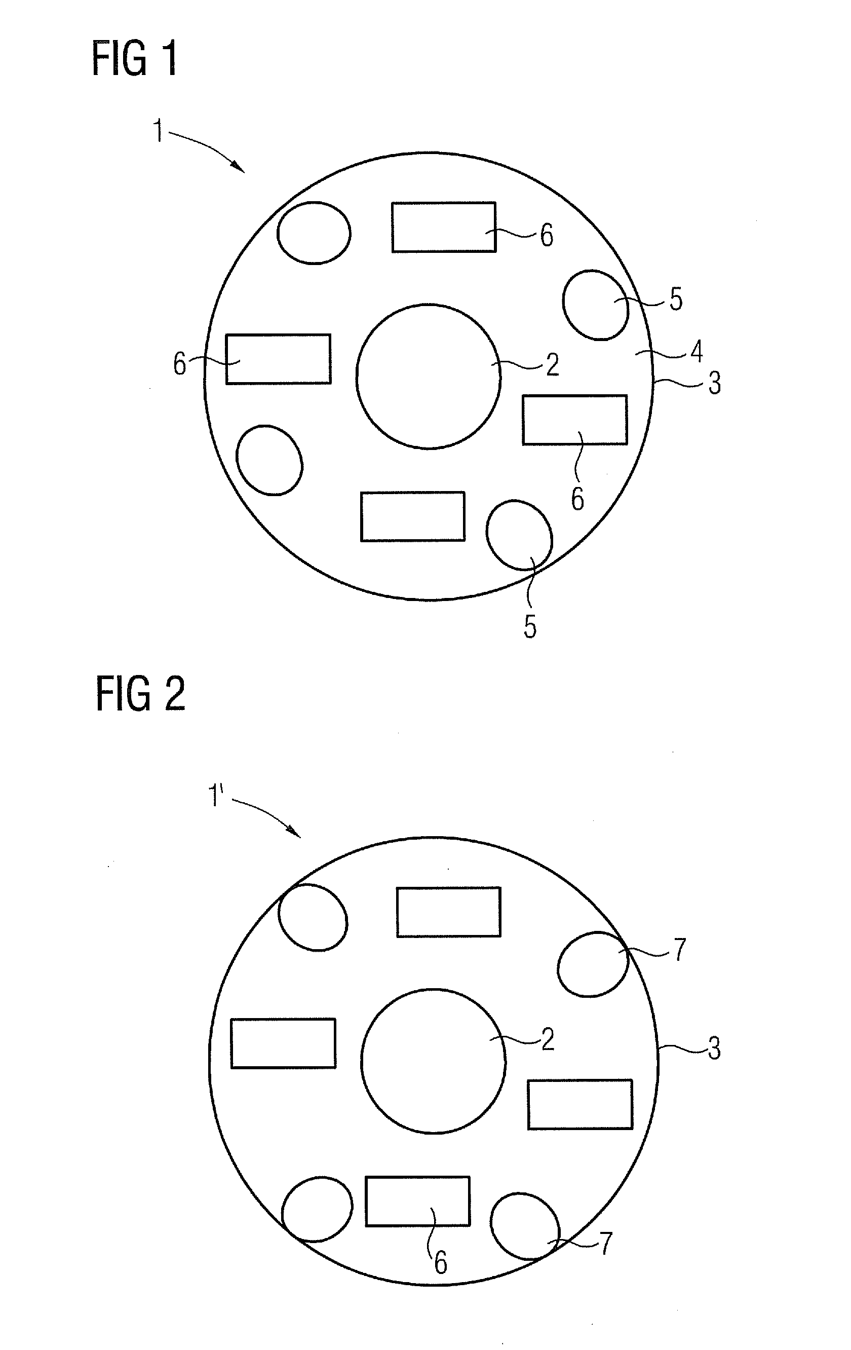
[0052]FIG. 1 shows a section through an inventive microcapsule 1 in a first embodiment. It comprises a magnetic nanoparticle 2 as the magnetic core, which can be formed on a basis of iron (III) oxide and / or iron (II,III) oxide. It has a diameter of around 80 nm. The outer casing 3 is formed by a support material 4. In the present example this is a biodegradable polymer.

[0053]Within the casing 3 the otherwise spherical microcapsule 1 also comprises a radioactive agent 5 (radioembolization agent), in this instance yttrium-90. Finally a marker material 6 is also provided within the casing 3, in this instance iodine, which serves as an x-ray marker.

[0054]The microcapsule 1 itself here has a diameter in the order of around five times the diameter of a red blood corpuscle, so that the microcapsule 1, when injected for example out of a catheter into a blood vessel supplying a tumor, remains lodged in the blood vessel within the tumor and can emit the radioactive radiation to destroy the tu...


PUM

PropertyMeasurementUnit
Diameteraaaaaaaaaa
Diameteraaaaaaaaaa
Diameteraaaaaaaaaa

Abstract

A microcapsule for the local treatment of a tumor is proposed. The microcapsule has a support material forming a casing for the microcapsule, an active agent that damages tumor cells, a marker material suitable for use as an x-ray marker, and at least one magnetic nanoparticle. The active agent in particular destroys the tumor cells.

Description

CROSS REFERENCE TO RELATED APPLICATIONS[0001]This application claims priority of German application No. 10 2010 022 926.1 filed Jun. 7, 2010, which is incorporated by reference herein in its entirety.FIELD OF THE INVENTION[0002]The invention relates to a microcapsule for the local treatment of a tumor, a method for positioning a magnetic gradient field guiding magnetic nanoparticles, in particular magnetic nanoparticles of a microcapsule, to a target location and / or holding them at the target location as well as an associated apparatus.BACKGROUND OF THE INVENTION[0003]Cancers have always represented a challenge for modern medicine. Conventional cancer therapies can generally provide the following measures:1. surgical removal of the tumor,2. chemotherapy,3. radiation therapy and4. a combination of the three measures listed above.[0004]Despite all the advances achieved with the abovementioned measures many patients may experience recurring tumors or metastases. The forms of therapy de...

Claims


Application Information

Patent Timeline
IPC IPC(8): A61B5/055A61K31/704A61P35/00A61N2/00A61K9/50A61K31/136B82Y5/00
CPCA61B19/22A61K51/1251A61B2017/00004A61B2019/2253A61B2019/5238A61B2019/524A61B2019/5251A61B2019/542A61B2019/5454A61B2019/5466A61B2019/5495A61K9/5094A61K31/136A61K31/704A61K49/0419A61M25/0105A61M25/0127A61M37/0069A61M2025/0166A61N5/1007A61B19/5244A61B34/73A61B2090/392A61B2090/3995A61B34/20A61B34/70A61B2090/376A61B2090/3762A61B2034/2051A61B2090/3954A61B2090/3966A61P35/00
Inventor MASCHKE, MICHAELKLINGENBECK, KLAUS
Owner SIEMENS AG
Learn More