Eureka AIR delivers breakthrough ideas for toughest innovation challenges, trusted by R&D personnel around the world.

Automated system for improved cooling of aluminum castings in sand molds

a technology of automatic cooling and aluminum castings, which is applied in the field of aluminum castings and metal castings, can solve the problems of odor and contamination of the plant area, sand molds require a longer cooling time, and need for cooling down, so as to improve the overall quality and mechanical properties of the castings, save space, and improve the overall quality of the castings. the effect of quality

Inactive Publication Date: 2011-12-15
TENEDORA NEMAK SA DE CV
View PDF5 Cites 7 Cited by
  • Summary
  • Abstract
  • Description
  • Claims
  • Application Information

AI Technical Summary

Benefits of technology

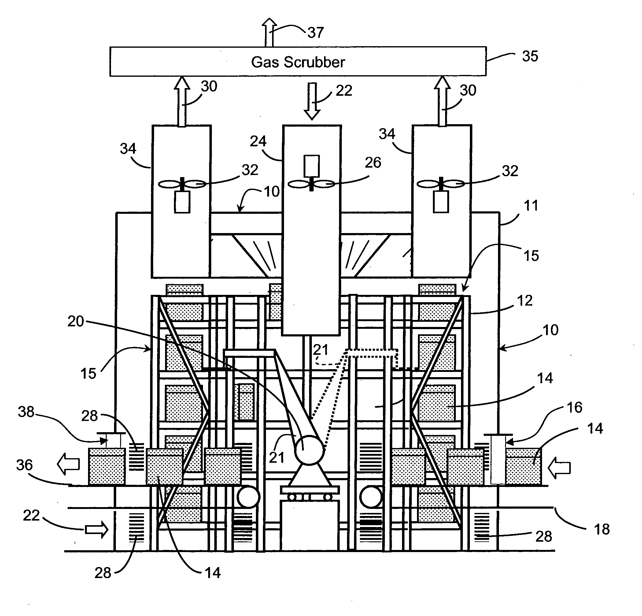
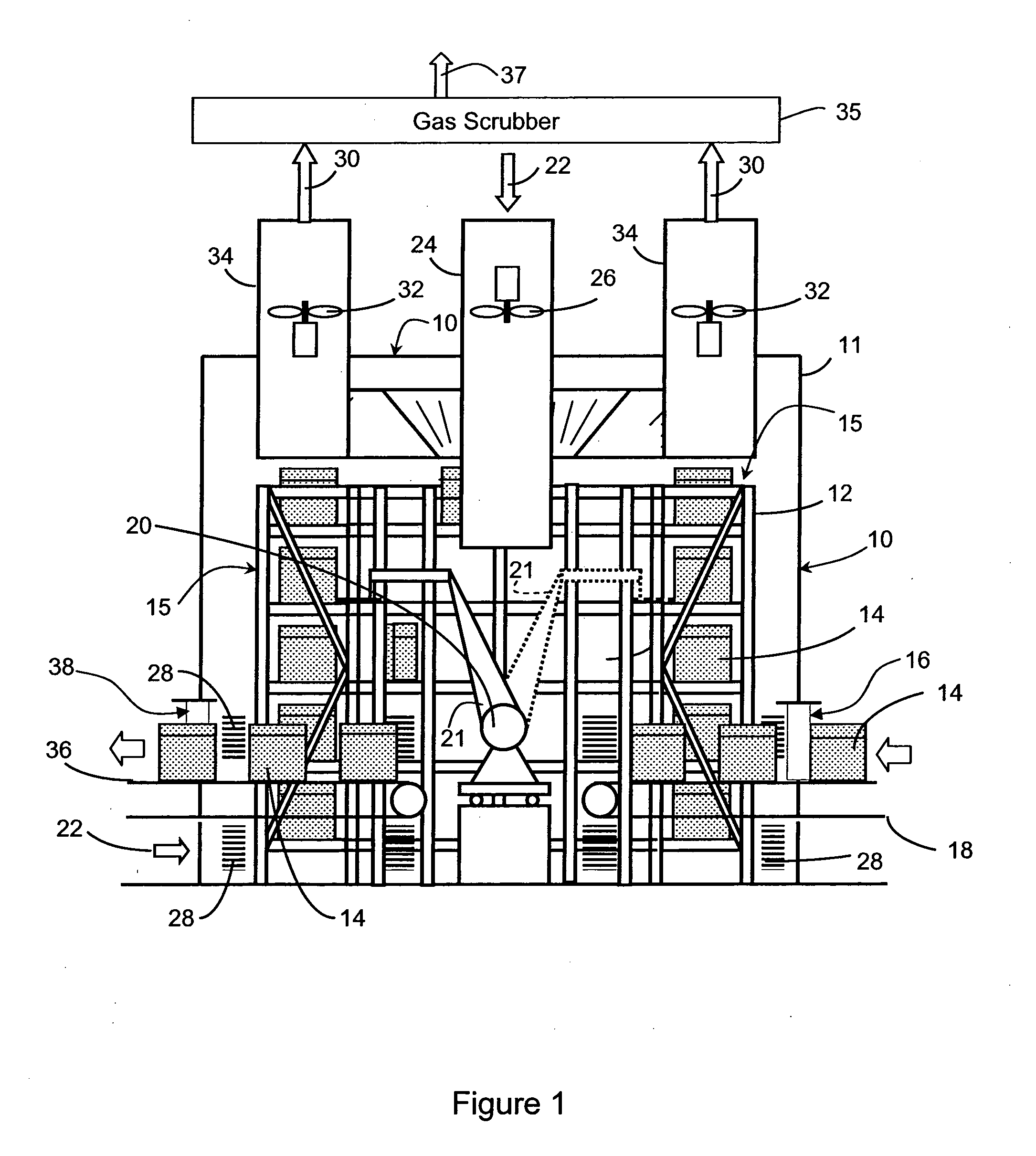
[0016]It is also a further advantage of the present invention that, not only is space saved in the foundry, but also by confining the forced air convection within an enclosed space, the fumes and vapors produced by the hot resin binder of molds and cores can be controlled and eliminated, providing a cleaner ambient atmosphere in the area.

Problems solved by technology

The time needed for cooling down the casting is longer if the mold is made of sand, since the sand mold package does not have the permanent mold's desirable heat-transfer properties for a rapid cooling, and therefore these sand molds require a longer time for cooling.
One of the other drawbacks of the usual current practice concerns liberation of noxious fumes and vapors from the sand molds and their cores caused by the heating of the resins used as binders of the sand molds, which causes odors and contamination of the plant area where the molds and their castings are cooled down.
This system has the disadvantage of still requiring a large plant space.

Method used


Image

  • Automated system for improved cooling of aluminum castings in sand molds
  • Automated system for improved cooling of aluminum castings in sand molds
  • Automated system for improved cooling of aluminum castings in sand molds

Examples


Embodiment Construction

[0024]A preferred embodiment of the invention will be described as applied to the cooling of sand molds containing aluminum alloys for manufacturing automotive motor parts, e.g. cylinder engine blocks and engine cylinder heads.

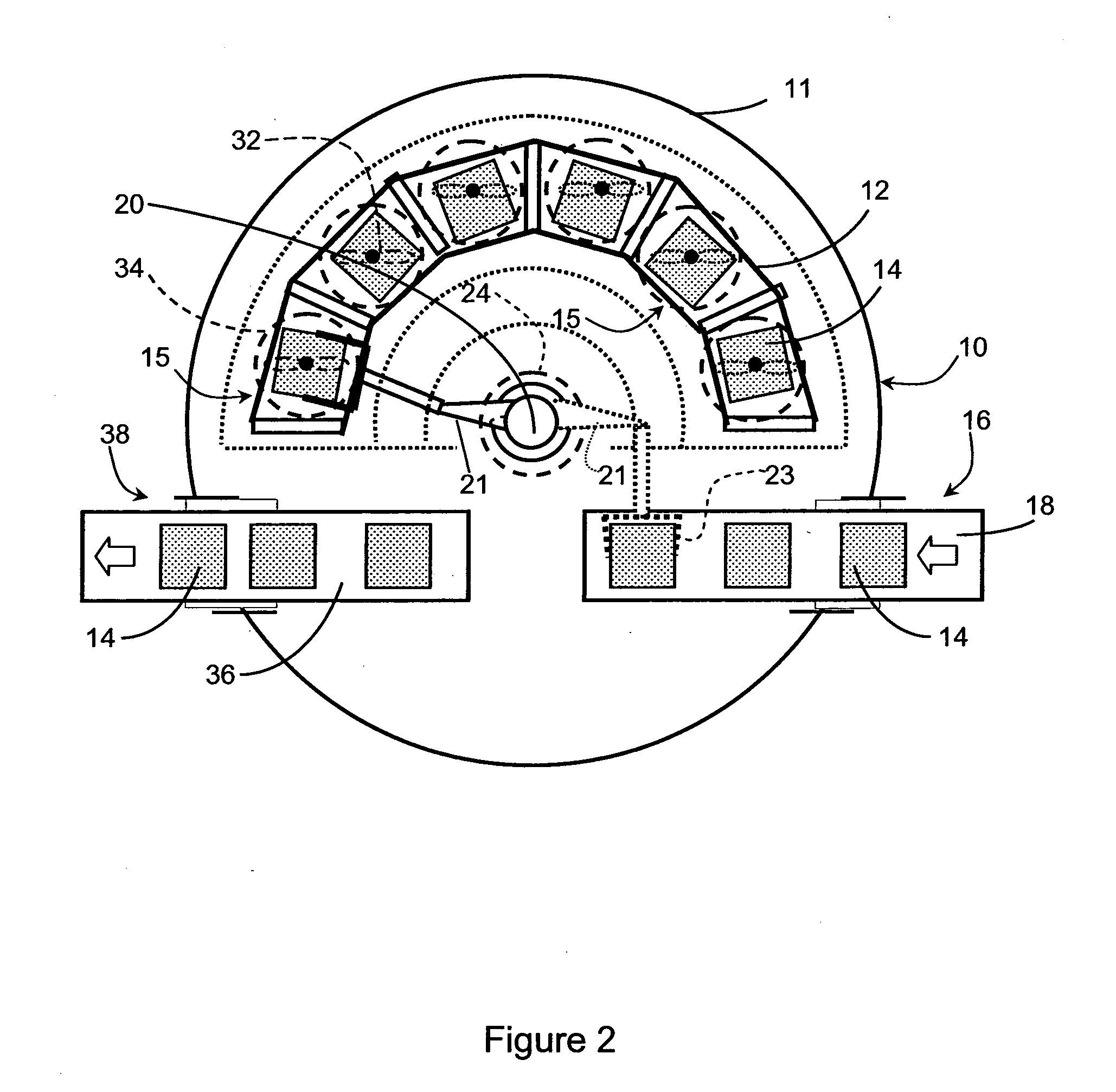
[0025]Referring to FIGS. 1 and 2, there is shown an apparatus for improved cooling of aluminum castings in sand molds comprising a cylindrical housing 10 containing a plurality of vertical shelves 12 which are distributed around at least a portion of the inside of the circular side wall 11 wall of said housing 10 for the purpose of storing sand molds 14 in a cooling environment, while the castings are solidifying. In the illustrated embodiment, each shelf in each unit of the vertical shelving 12 constitutes a single cooling station 15.

[0026]The hot newly cast sand molds containing molten metal 14 are introduced through a sand mold inlet port 16 via conveying feed means 18. From there, the robot 20 uses its arm 21 with clamp 23 (shown in dotted outline in FIG. ...


PUM

PropertyMeasurementUnit
Temperatureaaaaaaaaaa
Timeaaaaaaaaaa
Shapeaaaaaaaaaa

Abstract

An improved and efficient method and apparatus for convective cooling of cast sand molds containing molten metal, utilizing vertically-arrayed cooling stations (preferably arranged on a plurality of shelves inside a housing enclosure for temporarily storing said sand molds during their cooling from a molten temperature level to a lower solidification temperature. A draft of cooling air is circulated through said stations in said housing whereby the time for solidifying the molten metal in said cast sand molds is reduced as compared with passive air cooling of said molds. Robot means are provided for moving hot sand molds from a feeding port in said housing to said shelves and for moving cooled sand molds from said shelves to a delivery port in said housing. The robot means is programmed so that the time period of each mold is maintained within said housing according to the individual time required for the solidification of the metal in such individual mold (based on empirical data for typical solidification required for the given individual cast sand mold package or based on other appropriate discernible physical property attributable to achieved solidification).

Description

FIELD OF THE INVENTION[0001]The present invention relates to the field of foundries and metal casting. More particularly, the present invention teaches an improved automated and efficient system for cooling sand mold packages filled with molten metal by air convection cooling minimizing the space necessary for cooling down large numbers of sand mold packages with the additional advantages of improved quality of the castings and savings in capital and in operational costs.BACKGROUND OF THE INVENTION[0002]In the metal casting industry, molds containing molten metal must be cooled down sufficiently to solidify the metal before passing the casting on to the next steps in the process; such as extracting the casting from the mold and then eliminating the sand cores that were utilized to shape the piece to the desired geometry. In some processes using permanent molds, the cooling of the casting is accelerated by circulating a cooling fluid through certain metallic portions of the mold. The...

Claims


Application Information

Patent Timeline
IPC IPC(8): B22D46/00B22C9/00B22C23/00B22D27/04
CPCB22D30/00B22D47/00B22D45/00
Inventor SALINAS-PENA, GERARDOLEON-QUEZADA, MARIO ALBERTOMARTINEZ-RUIZ, JOSE AUGUSTOMONTERO-CANTU, RAMIRO
Owner TENEDORA NEMAK SA DE CV
Why Eureka
Eureka Blog
Learn More