Medical device or instrument having porous structure

a medical device and porous structure technology, applied in the field of medical devices or instruments, can solve the problems of occlusion of blood flow passages, affecting the accuracy of dimensional accuracy, and affecting the accuracy of ventricular assist devices, etc., and achieve the effect of robust structure and loss of dimensional accuracy

Inactive Publication Date: 2011-12-22
SUN MEDICAL TECH RES +1
View PDF7 Cites 47 Cited by
  • Summary
  • Abstract
  • Description
  • Claims
  • Application Information

AI Technical Summary

Benefits of technology

[0017]A first object of the present invention is to provide an inflow cannula for blood circulatory assist devices, having a robust structure and possessing a thrombus anchoring effect to allow thereby adhesion of endothelial cells to the inflow cannula, wherein the inflow cannula does not deform or exhibit loss of dimensional accuracy during the manufacture process.
[0018]A second object of the present invention is to provide the inflow cannula, comprising a textured surface formed by pores which have a uniform opening surface area and opening shape, whereby the thrombus anchoring effect is enhanced and the endothelial cells can be adhered to the inflow cannula even more stably as a result.
[0019]A third object of the present invention is to provide the inflow cannula having yet higher mechanical strength, and being yet easier to insert into the application site.

Problems solved by technology

Should part of such device or instrument be damaged and release, as a result, fragments or the like into the bloodstream, an embolism may occur.
In addition to the above-described mechanical strength issue, long-term use of an artificial heart or a ventricular assist device is complicated by the serious problem of circulatory deficit caused by thrombi.
For instance, a thrombus forming and growing in the blood pump may occlude blood flow passages or cause the pump to stop.
Even if the thrombus is very small, detachment thereof might occlude a peripheral blood vessel, thereby posing significant danger to life.
However, even if such materials are used in the devices or instruments that make up an artificial heart or a ventricular assist device, thrombi tend to form readily, for example, on the outer peripheral face of a cannula which is inserted into the heart, i.e., on the outer peripheral face of an inflow cannula.
In actuality, it has been found that insertion into the heart of a conventionally used inflow cannula made of titanium and having a smooth surface, i.e., having the surface smoothed by polishing or the like, may result in formation of thrombi on the surface of the cannula within a short period of time.
If a thrombus detaches in the left ventricle or the like, it enters the bloodstream at once and is carried into the body, where it may cause an infarction in a thin blood vessel.
This may give rise to conditions, such as cerebral infarction or renal infarction, that have a devastating impact on the patient.
The same problem besets devices or instruments other than the inflow cannula, such as blood pumps (in particular, the pump inner surface that is in contact with the blood), connectors or the like that make up as well an artificial heart or a ventricular assist device, and which are indwelling at sites where blood pools easily.
However, the number of cell divisions that endothelial cells can undergo is limited in practice, and hence endothelial cells do not reach up to sites that are removed at a distance from living tissue.
Therefore, covering the entire blood-contacting surface in the ventricular assist device with endothelial cells is next to impossible.
Removing the germs with antibiotics or the like is difficult, and sepsis may set in over time.

Method used


Image

  • Medical device or instrument having porous structure
  • Medical device or instrument having porous structure
  • Medical device or instrument having porous structure

Examples


examples

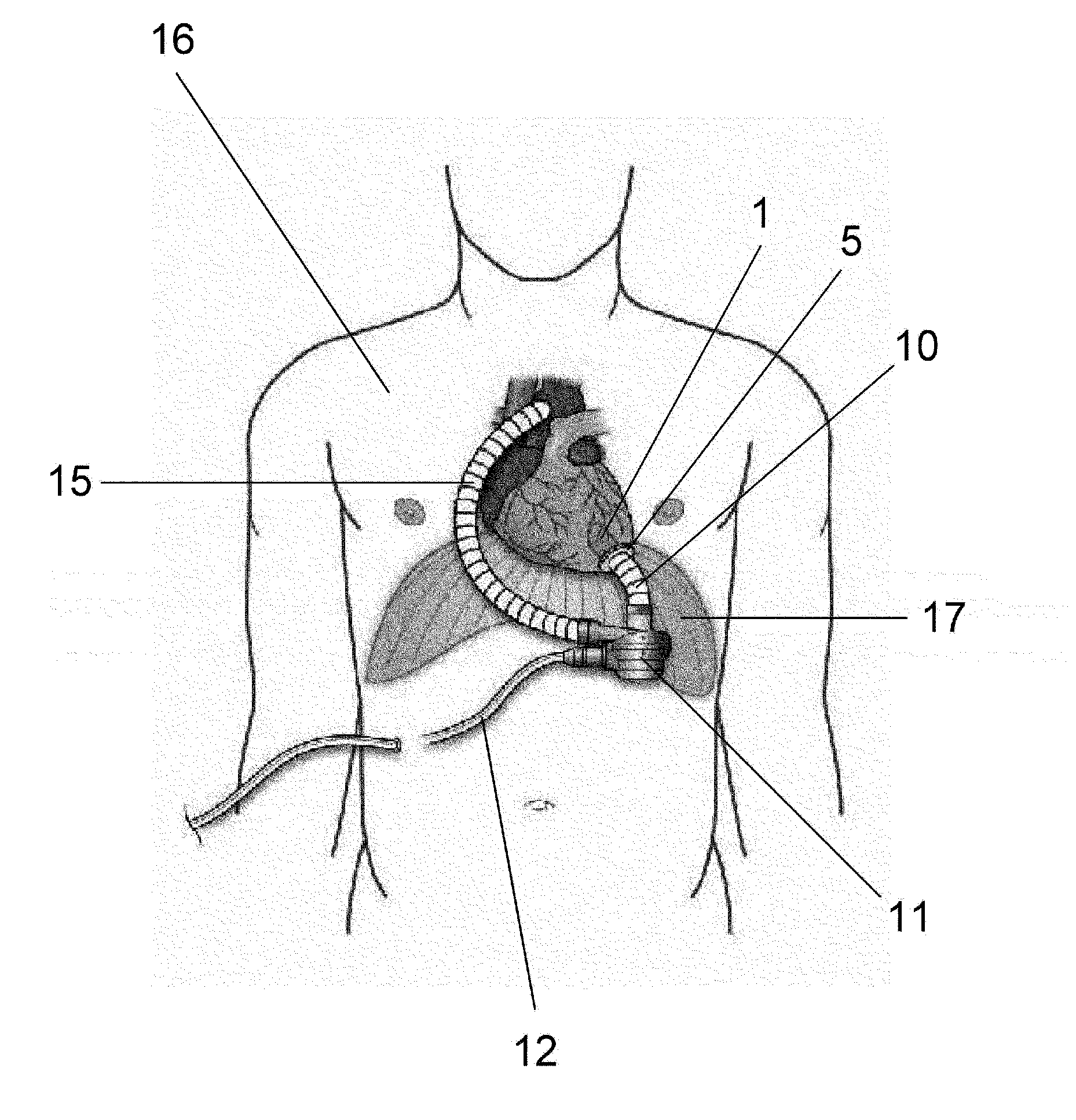
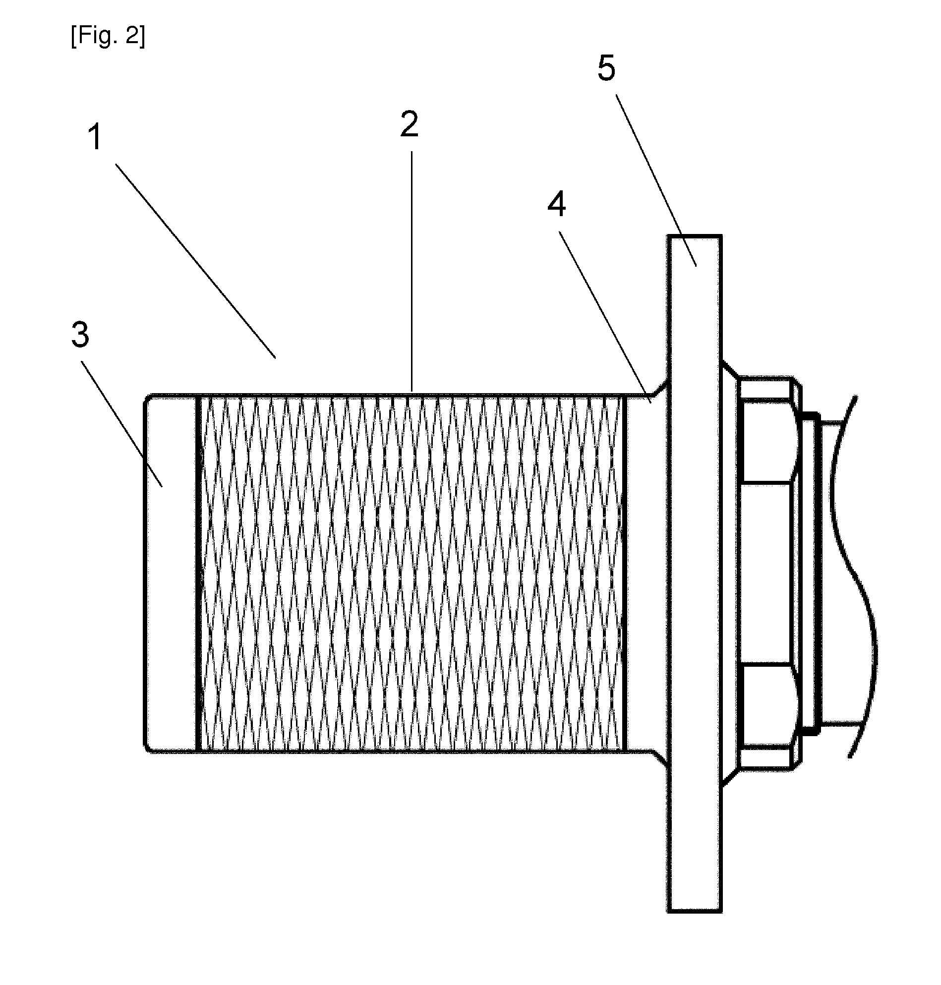
[0179]Two animal experiments were carried out using the inflow cannulas illustrated in FIGS. 2 to 5 (Two inflow cannulas were used on two respective calves (age 3 months, male, weight at implantation 86.5 kg; and age 3 months, male, weight at implantation 88.0 kg)). The calves were selectively sacrificed on POD 65 (post-operative day 65) and POD 63 (post-operative day 63). The implantation procedure was carried out through left thoracotomy with left ventricular pulsation. The above-described inflow cannula was inserted into the left ventricle, the blood pump was disposed in the thoracic cavity, and the outflow graft was joined to the descending aorta through end-to-side anastomosis. After implantation, the blood pump was driven stably at of 1864 to 1897 rpm and power consumption of 4.4 to 6.1 W. The health condition of the calves was good, and results of blood tests performed on them revealed no impaired renal function or the like, and no sings of infarction or the like caused by th...


PUM

PropertyMeasurementUnit
surface areaaaaaaaaaaa
particle size distributionaaaaaaaaaa
diameteraaaaaaaaaa

Abstract

The present invention relates to an inflow cannula for blood circulatory assist devices, having a robust structure and possessing a thrombus anchoring effect. Furthermore, the inflow cannula for blood circulatory assist devices does not deform or exhibit loss of dimensional accuracy during the manufacture process. These features are achieved by a porous structure formed of one or more linear elements or of a porous shaped article.

Description

TECHNICAL FIELD [0001]The present invention relates to a medical device or instrument having a porous structure with a thrombus anchoring function, the medical device or instrument allowing long-term indwelling use in vivo, and also relates to a method of manufacturing the medical device or instrument, and to use thereof.BACKGROUND ART [0002]In recent years, whole-body circulation has come to be assisted through the use of an artificial heart or the like if cardiac function is compromised owing to conditions such as heart failure or the like. Ventricular assist devices can temporarily replace the cardiac function, lost on account of, for instance, heart disease, external injury, or heart attack, until recovery of the cardiac function or while waiting for a heart transplant, or can replace cardiac function permanently, thereby keeping the patient alive, all of which underscore the importance of such devices.[0003]In particular, it is well known that left ventricular assist devices ar...

Claims


Application Information

Patent Timeline
Patent Type & Authority Applications(United States)
IPC IPC(8): A61M1/10A61M25/00B65H81/08
CPCA61L29/146A61M1/3659A61M1/122A61M1/3653A61M60/148A61M60/268A61M60/178
Inventor MIYAKOSHI, TAKAYUKITOKUNO, TOSHIMASAKITANO, TOMOYAYOSHINO, KAZUTAKASEKI, YASUO
Owner SUN MEDICAL TECH RES
Why Eureka
Try Eureka