
Hybrid laser arc welding process and apparatus

a laser arc welding and hybrid technology, applied in the field of welding methods, can solve the problems of trapped porosity in the deep penetrant laser beam welding technique, affecting the welding process, and affecting the welding effect of the laser beam, so as to eliminate porosity and gas pockets, and increase the welding depth

Active Publication Date: 2012-01-05
GENERAL ELECTRIC CO
View PDF2 Cites 28 Cited by
  • Summary
  • Abstract
  • Description
  • Claims
  • Application Information

AI Technical Summary

Benefits of technology

[0007]The present invention provides a welding method and apparatus that utilize a hybrid laser arc welding process in combination with a laser beam welding process that precedes the hybrid laser arc welding process to increase the weld depth and/or promote the elimination of porosity and gas poc

Problems solved by technology

Even though laser beam welding is known to have the various benefits noted above, deep penetrating laser beam welding techniques are known to be prone to trapped porosity.
As a result, the weld pool produced by laser beam welding tends to freeze very quickly, trapping gas-metal reaction products generated during the welding process.
Though the inclusion of an arc process in HLAW processes helps to reduce porosity in shallow welds, for example, weld depths of less than one-half inch (about one centimeter), porosity resulting from trapped gas bubbles is an issue when attempting to achieve greater weld depths.
The presence of porosity can significantly reduce the fatigue life of a weld joint and, therefore, a structure that contains the weld joint.
However, when used to weld large thick sections required in the construction of wind turbine towers, a significant drawback of the SAW process is low productivity, for example, resulting from the necessity to perform multiple passes at relatively low speeds, for example, about twenty to forty inches (about 50 to 100 cm) per minute.
Though preheating the components just prior to welding might achieve a lower cooling rate to allow gas bubbles to escape the weld pool, in practice a component may require being heated to nearly three-quarters of its melting temperature, which is both expensive and can have deleterious effects on the base material properties of the component.
Following laser beam welding with a second laser beam welding treatment to release the gas bubbles has also proven to be ineffective, since the weld pool produced by the second treatment also tends to freeze too quickly to allow gas bubbles to float free of the weld pool.

Method used


Image

  • Hybrid laser arc welding process and apparatus
  • Hybrid laser arc welding process and apparatus

Examples


Embodiment Construction

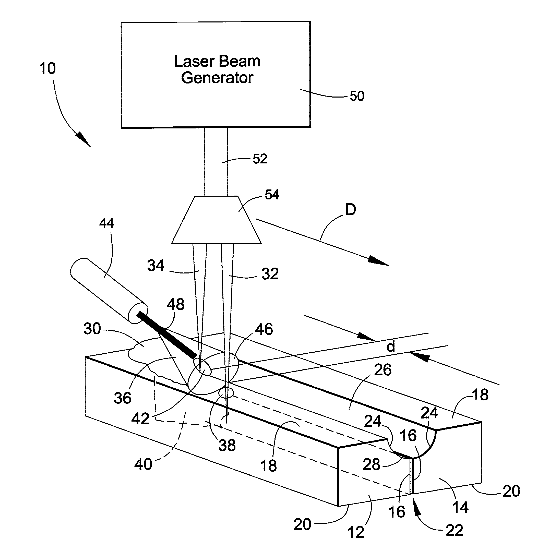
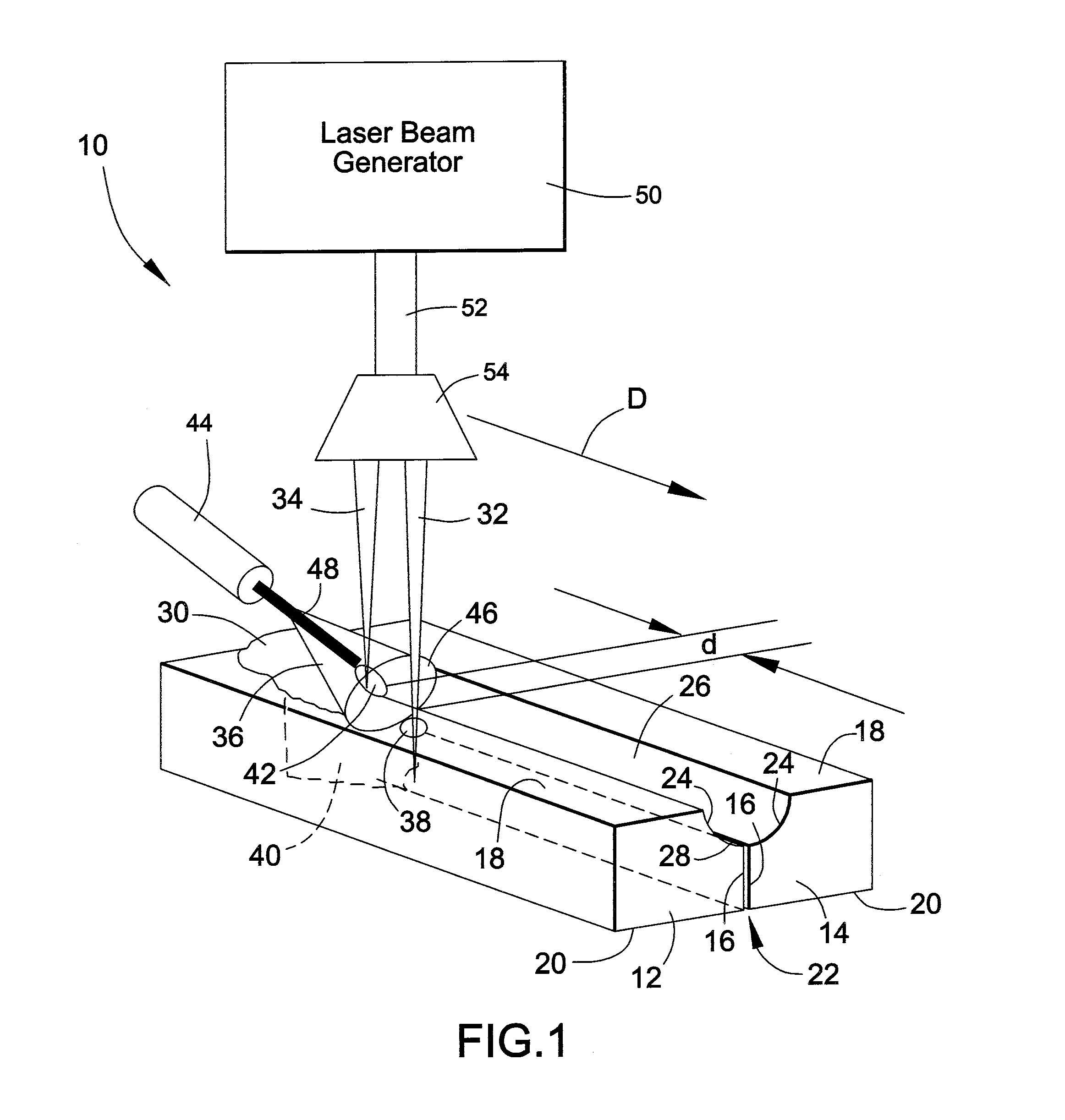
[0013]FIG. 1 represents a welding apparatus 10 for conducting a multistage welding process that utilizes what may be a generally conventional hybrid laser arc welding process, but modified by the inclusion of a second laser beam that is projected onto the intended weld joint ahead of the hybrid laser arc welding process. The multistage welding process preferably yields a relatively deep-penetrating weldment that is capable of being free of porosity resulting from gas bubbles that evolve during laser beam welding. The welding process is particularly well suited for fabricating components that require welding at relative thick sections, for example, one centimeter or more, as is the case for fabricating various components used in power generation applications, including the construction of wind turbine towers, as well as components intended for a wide variety of other applications, including aerospace, infrastructure, medical, industrial applications, etc.

[0014]FIG. 1 represents a pai...


PUM

PropertyMeasurementUnit
Lengthaaaaaaaaaa
Poweraaaaaaaaaa
Distanceaaaaaaaaaa

Abstract

A welding method and apparatus for welding workpieces together by conducting a laser beam welding process on a joint region that includes a weld seam defined by and between faying surfaces of the workpieces, and then conducting a hybrid laser arc welding process on the joint region. The laser beam welding process entails causing a first laser beam to travel along the joint region, penetrate the weld seam and form a weldment. The hybrid laser arc welding process remelts the weldment by simultaneously causing an electric arc and a second laser beam to overlap and travel along the joint region and form a weld pool in the weldment. On cooling, a weld joint is formed within the joint region and its weld seam.

Description

BACKGROUND OF THE INVENTION[0001]The present invention generally relates to welding methods. More particularly, this invention is directed to a welding process that utilizes a hybrid laser arc welding technique in which laser beam welding and arc welding simultaneously occur in the same weld pool, and further utilizes a second laser beam welding technique that precedes the hybrid laser arc welding technique to increase the weld depth and / or promote the elimination of porosity and gas pockets in the resulting weld joint.[0002]Low-heat input welding processes, and particularly high-energy beam welding processes such as laser beam and electron beam welding (LBW and EBW, respectively) operated over a narrow range of welding conditions, have been successfully used to produce crack-free weld joints in a wide variety of materials, including but not limited to alloys used in turbomachinery. An advantage of high-energy beam welding processes is that the high energy density of the focused las...

Claims


Application Information

Patent Timeline
IPC IPC(8): B23K26/00
CPCB23K9/173B23K26/0604B23K26/0676B23K26/1429F05B2240/10B23K28/02B23K2201/006F05B2230/234B23K26/26B23K26/348B23K2101/006
Inventor NOWAK, DANIEL ANTHONYDIMASCIO, PAUL STEPHEN
Owner GENERAL ELECTRIC CO
Learn More