Treatment of Flue Gas From an Oxyfuel Combustion Process

a technology of oxyfuel and flue gas, which is applied in the direction of liquefaction, hydrogen sulfide, and combustion gas purification/modification, etc., can solve the problem of high combustion temperature, which is not practical in a furnace or boiler

Inactive Publication Date: 2012-01-12
AIR PROD & CHEM INC
View PDF4 Cites 33 Cited by
  • Summary
  • Abstract
  • Description
  • Claims
  • Application Information

AI Technical Summary

Benefits of technology

[0028]The present invention removes at least a significant quantity of CO present in a flue gas generated by oxyfuel combustion of a fuel, and reduces not only the emission concentration of CO, but also the total amount of CO that is vented to the atmosphere. One advantage of the present invention is that, in preferred embodiments, the method and apparatus also removes at least a significant quantity NO from the flue gas, either by conversion to NO2 (which may be removed using existing NO2 technologies), or by conversion to N2 which can be released into the atmosphere without limitation thereby avoiding the need for NO2 removal technology. Preferred embodiments of the present invention are also compatible with, and may therefore be integrated with, existing carbon dioxide recovery and / or SOx removal technologies.
[0029]According to a second aspect of the present invention, there is provided apparatus for removing CO from flue gas comprising carbon dioxide, CO and at least one non-condensable gas, said apparatus comprising:
[0030]an oxyfuel combustion system for generating said flue gas by oxyfuel combustion of a fuel; and
[0031]a pressurizable catalytic reactor system comprising at least one catalyst bed comprising a CO-oxidation catalyst, for converting CO from said flue gas in the presence of O2 at a first elevated temperature and at a first elevated pressure to carbon dioxide, to produce carbon dioxide-enriched gas comprising at least a portion of said non-condensable gas(es).BRIEF DESCRIPTION OF SEVERAL VIEWS OF THE DRAWINGS
[0032]FIG. 1 is a simplified flow sheet depicting one embodiment of the present invention;
[0033]FIG. 2 is a simplified flow sheet depicting a second embodiment of the present invention;

Problems solved by technology

This process would result in an absence of nitrogen (N2) in the flue gas, together with a very high combustion temperature which would not be practical in a furnace or boiler.

Method used


Image

  • Treatment of Flue Gas From an Oxyfuel Combustion Process
  • Treatment of Flue Gas From an Oxyfuel Combustion Process
  • Treatment of Flue Gas From an Oxyfuel Combustion Process

Examples


example

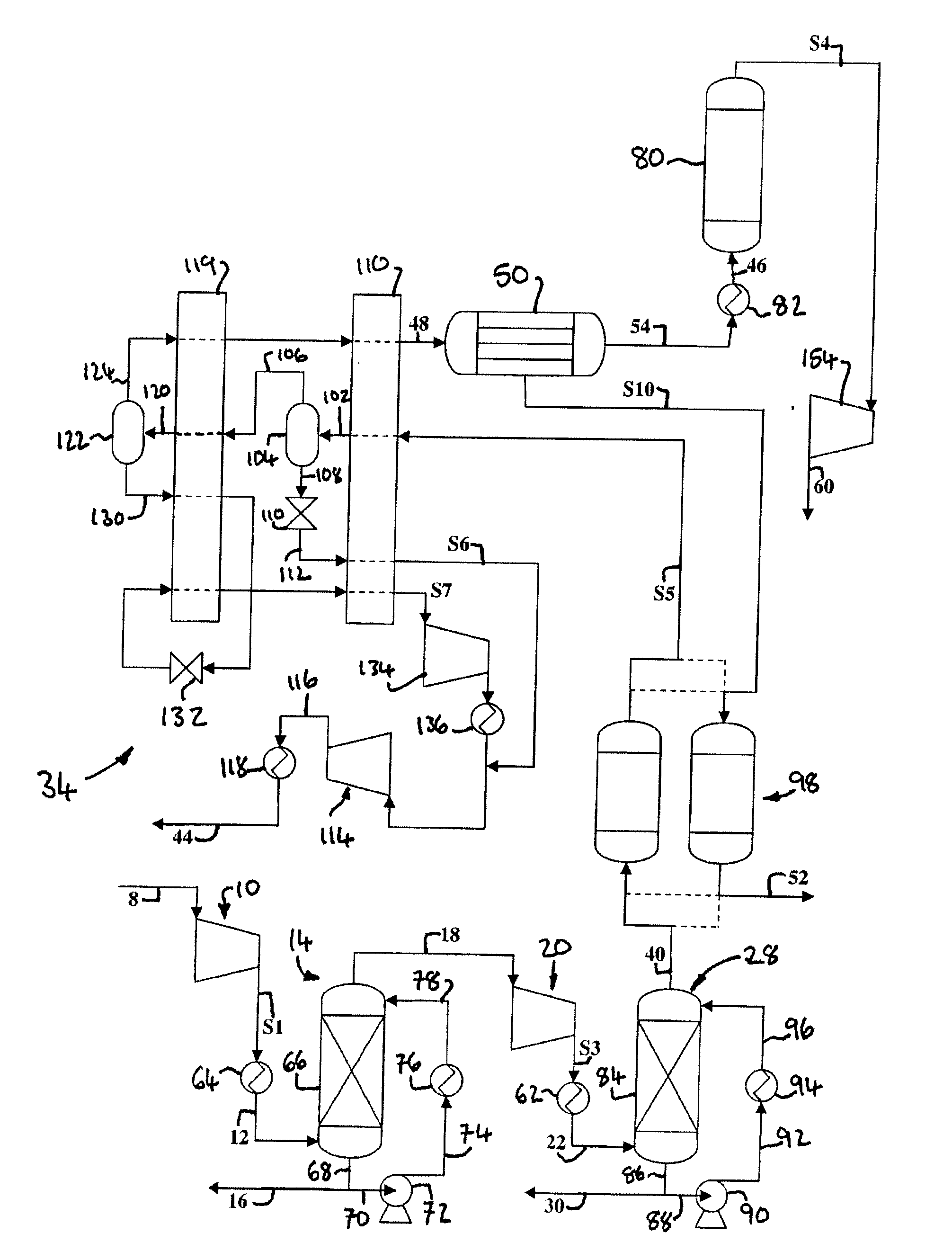
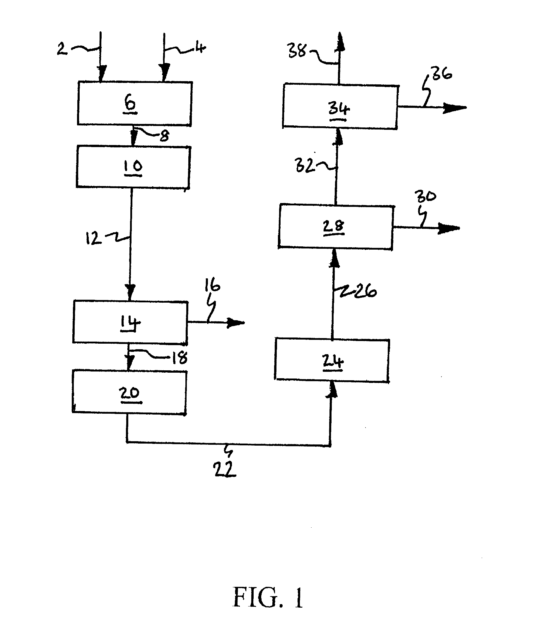
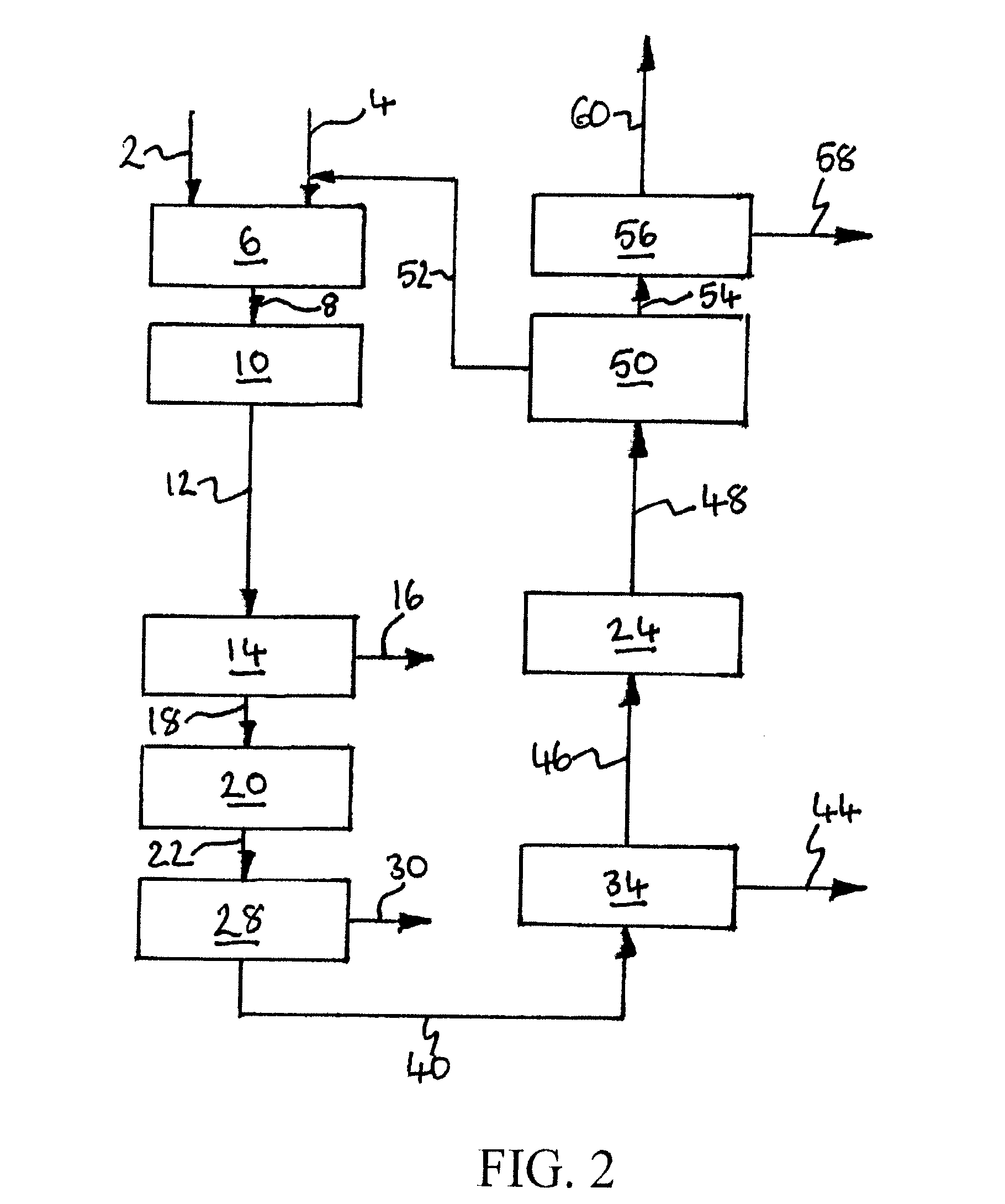
[0230]Computer simulations using the APSEN™ Plus software (version 2006.5; © Aspen Technology, Inc.) have been carried out in respect of the embodiments depicted in FIGS. 3 to 5. For each embodiment, a first simulation has been carried out on the basis that there is sufficient catalyst in the catalyst bed(s) to achieve 90% CO conversion, and a second simulation has been carried out on the basis that there is no catalyst in the bed(s). The results of the simulations are presented in the following heat and mass balance tables.

TABLE 2Embodiment of FIG. 3 (with catalyst)Stream—8121618222630323638PressureBar1.0115.0015.0015.0030.0030.0030.0030.00120.002.00(MPa)(0.1)(1.5)(1.5)(1.5)(3)(3)(3)(3)(12)(0.2)Temperature° C.30.0930.0065.0065.00160.0030.0034.1540.0030.0026.67Flow Ratekg / s150.6150.66.8143.8143.8143.81.4142.5107.734.6Armol %2.7112.7110.0052.8672.8672.8710.0022.9180.4558.906CO2mol %70.51870.5183.15474.48474.48474.7590.76175.97196.66226.714N2mol %15.75115.7510.01316.65716.65716.6760.0...


PUM

PropertyMeasurementUnit
temperatureaaaaaaaaaa
pressureaaaaaaaaaa
temperatureaaaaaaaaaa

Abstract

Carbon monoxide (CO) may be removed from flue gas generated by oxyfuel combustion of a hydrocarbon or carbonaceous fuel, by contacting the flue gas, or a CO-containing gas derived therefrom, at a first elevated temperature, e.g. at least 80° C., and at a first elevated pressure, e.g. at least 2 bar (0.2 MPa), with at least one catalyst bed comprising a CO-oxidation catalyst in the presence of oxygen (O2) to convert CO to carbon dioxide and produce carbon dioxide-enriched gas. The carbon dioxide produced from the CO may be recovered from the carbon dioxide-enriched gas using conventional carbon dioxide recovery techniques. NO in the flue gas may also be oxidized to nitrogen dioxide (NO2) and removed using conventional NO2 removal techniques, or may be reduced in the presence of a reducing gas to nitrogen (N2) which does not have to be removed from the gas.

Description

BACKGROUND OF THE INVENTION[0001]The present invention relates primarily to a method for removing carbon monoxide (CO) from flue gas generated by oxyfuel combustion of a fuel such as a hydrocarbon fuel; a carbonaceous fuel; or biomass. The method may also be used to remove nitric oxide (NO) from the flue gas. The invention has particular application in the processing of flue gas from an oxyfuel combustion process in a pulverized coal fired power station.[0002]The term “SOx” means oxides of sulfur and includes sulfur dioxide (SO2) and sulfur trioxide (SO3). The term “NOx” means oxides of nitrogen and includes primarily NO and nitrogen dioxide (NO2). NOx may comprise one or more other oxides of nitrogen including N2O, N2O4 and N2O3.[0003]It has been asserted that one of the main causes of global warming is the rise in greenhouse gas contamination in the atmosphere due to anthropological effects. The main greenhouse gas which is being emitted, carbon dioxide (CO2), has risen in concent...

Claims


Application Information

Patent Timeline
Patent Type & Authority Applications(United States)
IPC IPC(8): B01D53/62B01D53/56B01J8/00C01B31/20C01B32/50
CPCB01D53/002Y02E20/12B01D53/047B01D53/1456B01D53/229B01D53/75B01D53/864B01D53/8646B01D2255/2073B01D2255/20761B01D2256/22B01D2257/302B01D2257/404B01D2257/502B01D2257/80B01D2258/0283F23G7/07F23J2215/40F23J2215/50F25J3/067F25J2205/40F25J2205/66F25J2205/80F25J2205/82F25J2210/70F25J2220/02F25J2220/04F25J2220/82F25J2220/84F25J2230/30F25J2230/32F25J2230/80F25J2240/90Y02C10/12Y02E20/344B01D53/0462Y02C20/40Y02E20/34
Inventor WRIGHT, ANDREW DAVIDWHITE, VINCENTGOLDEN, TIMOTHY CHRISTOPHER
Owner AIR PROD & CHEM INC
Why Eureka
Try Eureka