
Radiographic image detector

Inactive Publication Date: 2012-01-26
TOKUYAMA CORP +3
View PDF4 Cites 14 Cited by
  • Summary
  • Abstract
  • Description
  • Claims
  • Application Information

AI Technical Summary

Benefits of technology

[0020]According to the present invention, extremely feeble ultraviolet rays produced upon conversion from radiation by the scintillator can be detected with high sensitivity. Thus, a radiographic image detector excellent in position resolution and count rate characteristic can be provided. Moreover, the radiographic image detector of the present invention can easily upsize the sensitive volume, and can be manufactured at a low cost. Hence, the radiographic image detector of the present invention is of immense value in the fields of medicine, industry, security, etc.

Problems solved by technology

However, the gas used therein has a low atomic weight, and thus shows low stopping power against photons having high energy, such as hard X-rays and gamma rays.
The particle beam image detector, therefore, posed the problem of low detection sensitivity to these photons.
Consequently, such detectors, when used as radiographic image detectors, have posed the problem of declining in position resolution and count rate characteristic.
Since chemically unstable gas molecules need to be used, moreover, the problem has occurred that the gas molecules themselves deteriorate, or the gas molecules deposit on the electrode of the detector.
These problems have posed difficulty in operating the detectors stably for a long term (see Non-Patent Document 2).
According to this method, the above-mentioned decreases in position resolution and count rate characteristic and the problem about the stability of operation are considered to be avoidable, but it has been unsuccessful to sufficiently increase a multiplication factor in multiplying or amplifying the electrons by the gas multiplication detector.
As a result, very feeble ultraviolet rays generated from the scintillator have not been detectable with satisfactory sensitivity.
To date, there have been no attempts to prepare an apparatus which can detect a radiographic image by such a method using a photoelectric conversion substance.

Method used


Image

  • Radiographic image detector
  • Radiographic image detector
  • Radiographic image detector

Examples


example 1

Preparation of Scintillator

[0076]In the present Example, a lanthanum fluoride crystal containing neodymium as a luminescence center element was used as a scintillator. The lanthanum fluoride crystal containing neodymium was produced using a crystal production apparatus by the Czochralski method. Lanthanum fluoride and neodymium fluoride, each having purity of 99.99% or more, were used as raw materials. First, 2,700 g of lanthanum fluoride and 300 g of neodymium fluoride were weighed, mixed together thoroughly, and charged into a crucible.

[0077]Then, the crucible charged with the above materials was installed within a chamber of the crystal production apparatus. After the interior of the chamber was evacuated under vacuum to 1.0×10⁻³ Pa or less by use of a vacuum evacuation device, a mixed gas consisting of tetrafluoromethane and argon with high purity was introduced into the chamber to replace the atmosphere inside with the gas. The pressure inside the chamber after gas replacement ...

examples 2

Scintillator

[0091]A lanthanum fluoride crystal containing neodymium as a luminescence center element, which was produced in Example 1, was used as the scintillator.

[0092]A gas multiplication ultraviolet image detector was prepared in the following manner:

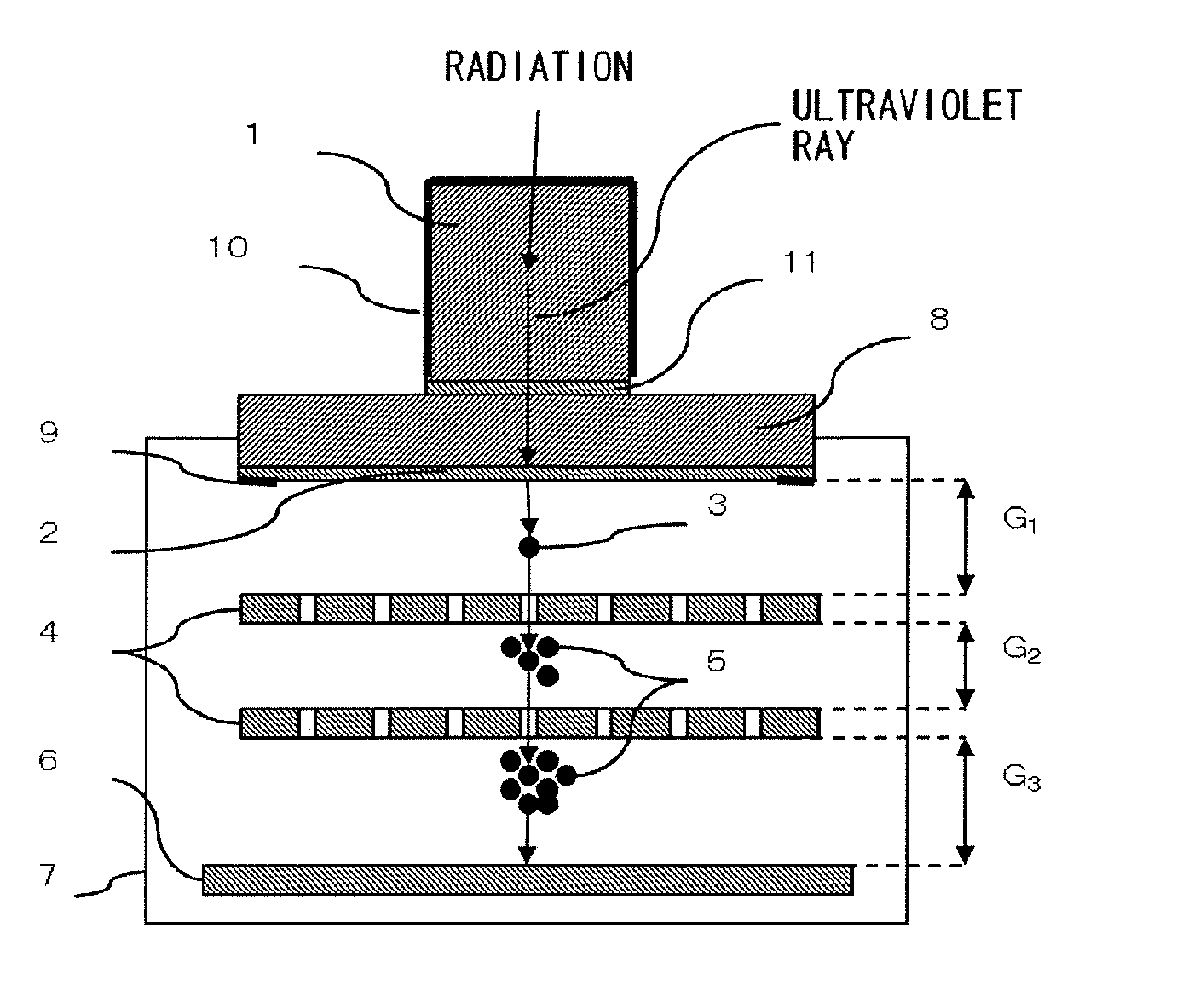
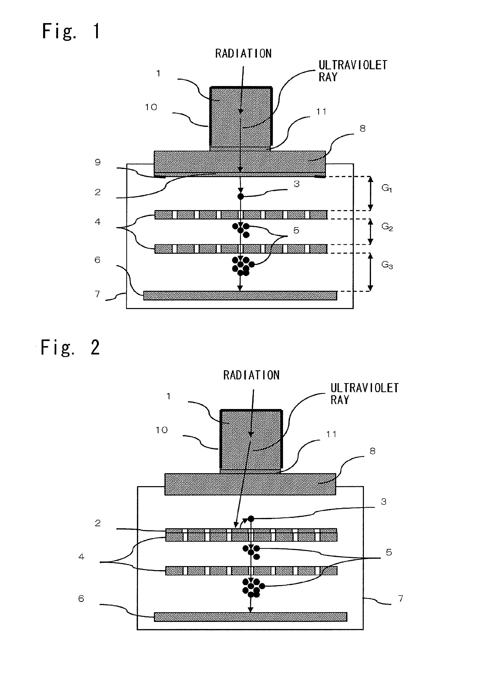
[0093]As shown in FIG. 2, two gas electron multipliers and a pixel electrode were installed parallel in this sequence within a chamber having an opening, starting on the side nearer the opening, and the opening was sealed with an ultraviolet entrance window. The distance between the ultraviolet entrance window and the gas electron multiplier at the first stage was 2.5 mm, the distance between the gas electron multiplier at the first stage and the gas electron multiplier at the subsequent stage was 2 mm, and the distance between the gas electron multiplier at the subsequent stage and the pixel electrode was 2 mm. As the gas electron multiplier at the first stage, there was used a plate-shaped multilayer body comprising many metal lay...

example 3

Preparation of Scintillator

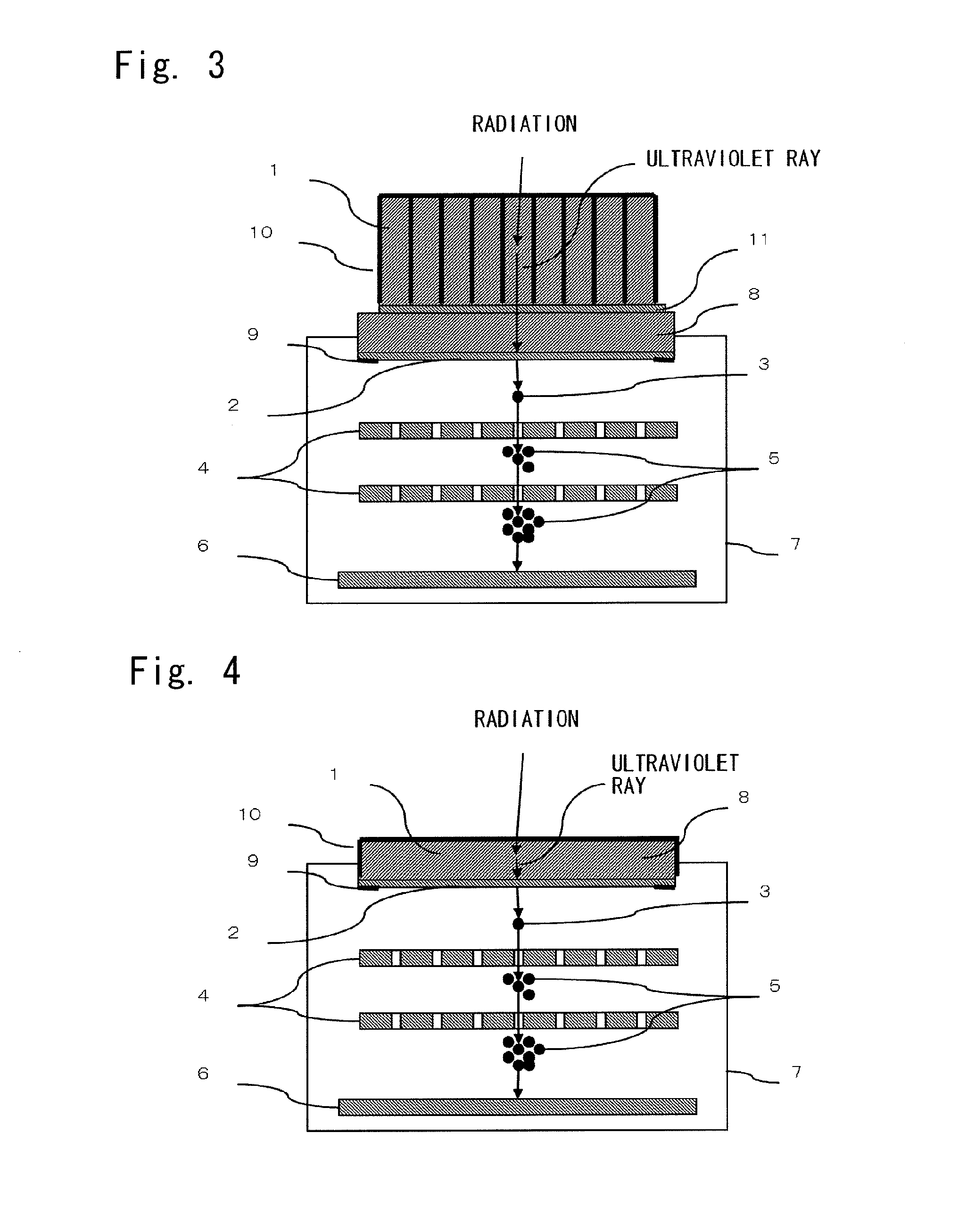
[0100]The lanthanum fluoride crystal containing neodymium as a luminescence center element, which was produced in Example 1, was used as the scintillator. This scintillator was processed into a 3×3×10 mm3 rectangular parallelepiped by a wire saw provided with a diamond wire, and was then optically polished on all surfaces. Of the optically polished surfaces, the one surface measuring 3×3 mm2 was used as an ultraviolet emergence surface, while the four surfaces except the ultraviolet emergence surface and the surface opposing it were coated with an ultraviolet reflective film comprising Teflon. Nine of the so prepared scintillators were rendered ready for use, and each scintillator was arranged such that its ultraviolet emergence surface was placed in the same plane, whereby a scintillator array in a 3×3 arrangement was prepared.

[0101]A gas multiplication ultraviolet image detector was prepared in the same manner as in Example 1.

[0102]In the gas multiplicat...


PUM


Abstract

[Problems to be Solved] It is an object of the present invention to provide a novel radiographic image detector which can detect radiation, such as hard X-rays or γ-rays, with high sensitivity and which is excellent in position resolution and count rate characteristic.[Means to Solve the Problems] A radiographic image detector comprises a combination of a scintillator, such as a lanthanum fluoride crystal containing neodymium, for converting incident radiation into ultraviolet rays; and a gas multiplication ultraviolet image detector for converting ultraviolet rays into electrons, amplifying such electrons by use of a gas electron avalanche phenomenon, and detecting the electrons. The radiographic image detector is characterized in that the gas multiplication ultraviolet image detector is basically constituted by a photoelectric conversion substance, such as cesium iodide or cesium telluride, for converting ultraviolet rays into electrons; a gas electron multiplier for amplifying electrons by use of the gas electron avalanche phenomenon; and a pixel electrode having an amplification function and a detection function.

Description

TECHNICAL FIELD[0001]This invention relates to a novel radiographic image detector. The radiographic image detector can be used preferably in medical fields such as positron emission tomography and X-ray CT, industrial fields such as various nondestructive tests, and security fields such as radiation monitors and inspection of personal belongings.BACKGROUND ART[0002]Radiation application technologies (i.e., technologies utilizing radiation) cover a wide range of fields, including medical fields such as positron emission tomography and X-ray CT, industrial fields such as various nondestructive tests, and security fields such as radiation monitors and inspection of personal belongings, and are making marked progress even now.[0003]Radiographic image detectors are constituent technologies occupying an important position in the radiation application technologies. With the progress of the radiation application technologies, the radiographic image detectors are required to achieve higher ...

Claims


Application Information

Patent Timeline
IPC IPC(8): G01T1/202G01T1/20
CPCG01T1/28H01J47/02H01J31/49G01T1/20H01L27/14
Inventor FUKUDA, KENTAROISHIZU, SUMITOKAWAGUCHI, NORIAKISUYAMA, TOSHIHISAYOSHIKAWA, AKIRAYANAGIDA, TAKAYUKIYOKOTA, YUIKUBO, HIDETOSHITANIMORI, TORUSEKIYA, HIROYUKI
Owner TOKUYAMA CORP
Learn More