
Apparatus for Treating a Substance with Wave Energy from Plasma and an Electrical Arc

a technology of wave energy and apparatus, applied in the field of apparatus for processing materials with plasma and electrical arc, can solve the problems of untapped energy source, small particle size, and difficulty in filtering small particles

Inactive Publication Date: 2012-01-26
FORET PLASMA LABS
View PDF6 Cites 24 Cited by
  • Summary
  • Abstract
  • Description
  • Claims
  • Application Information

AI Technical Summary

Benefits of technology

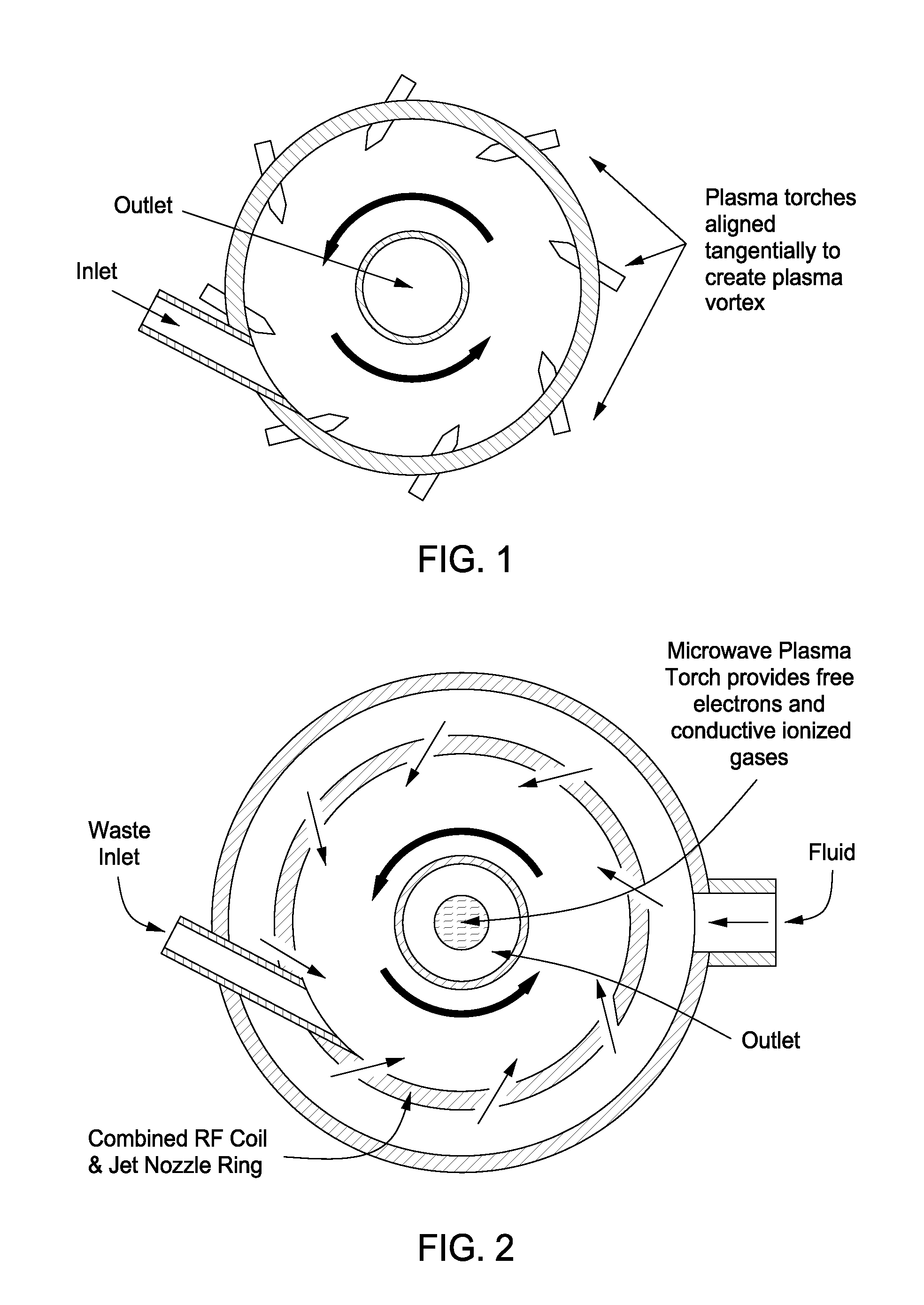
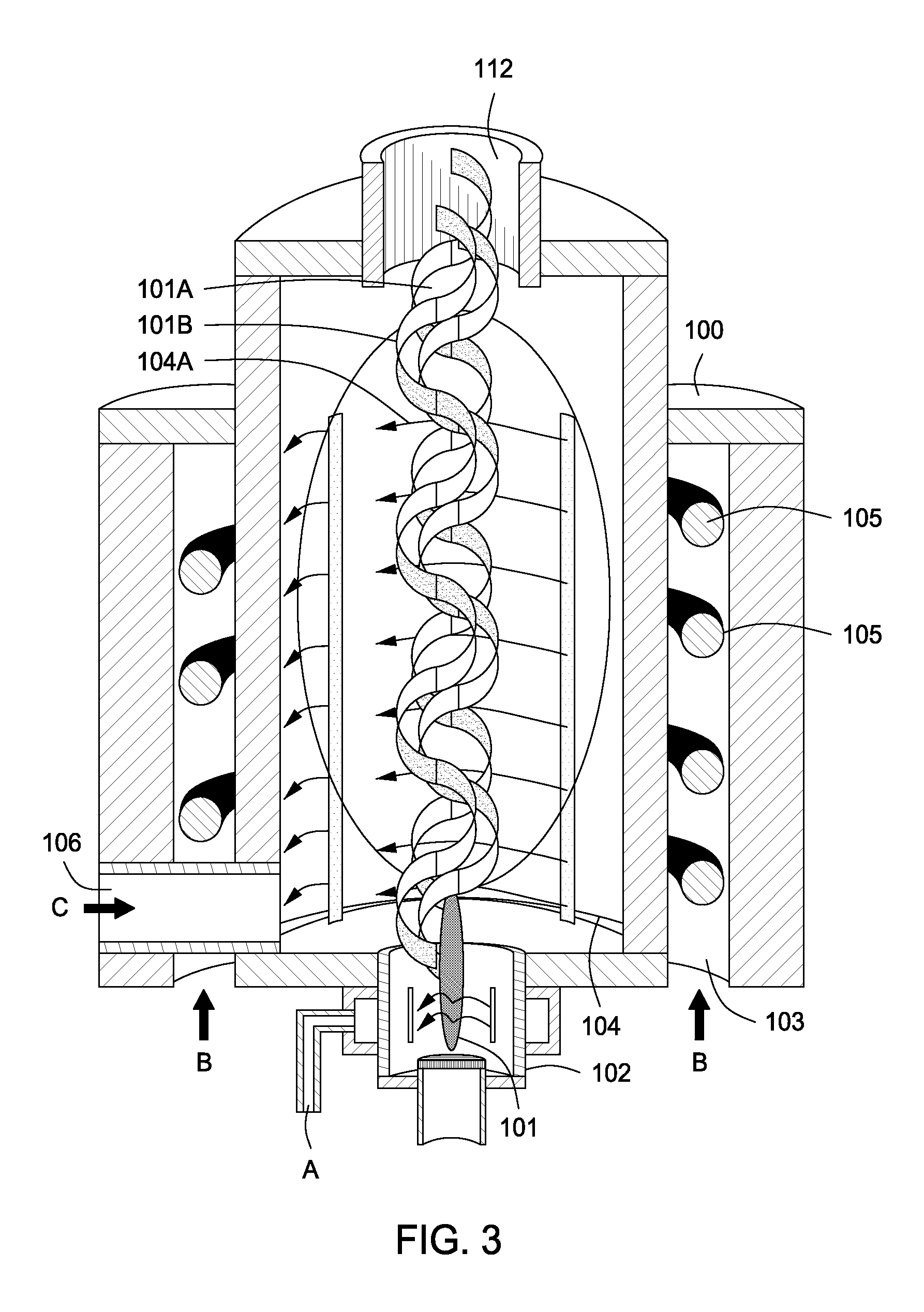
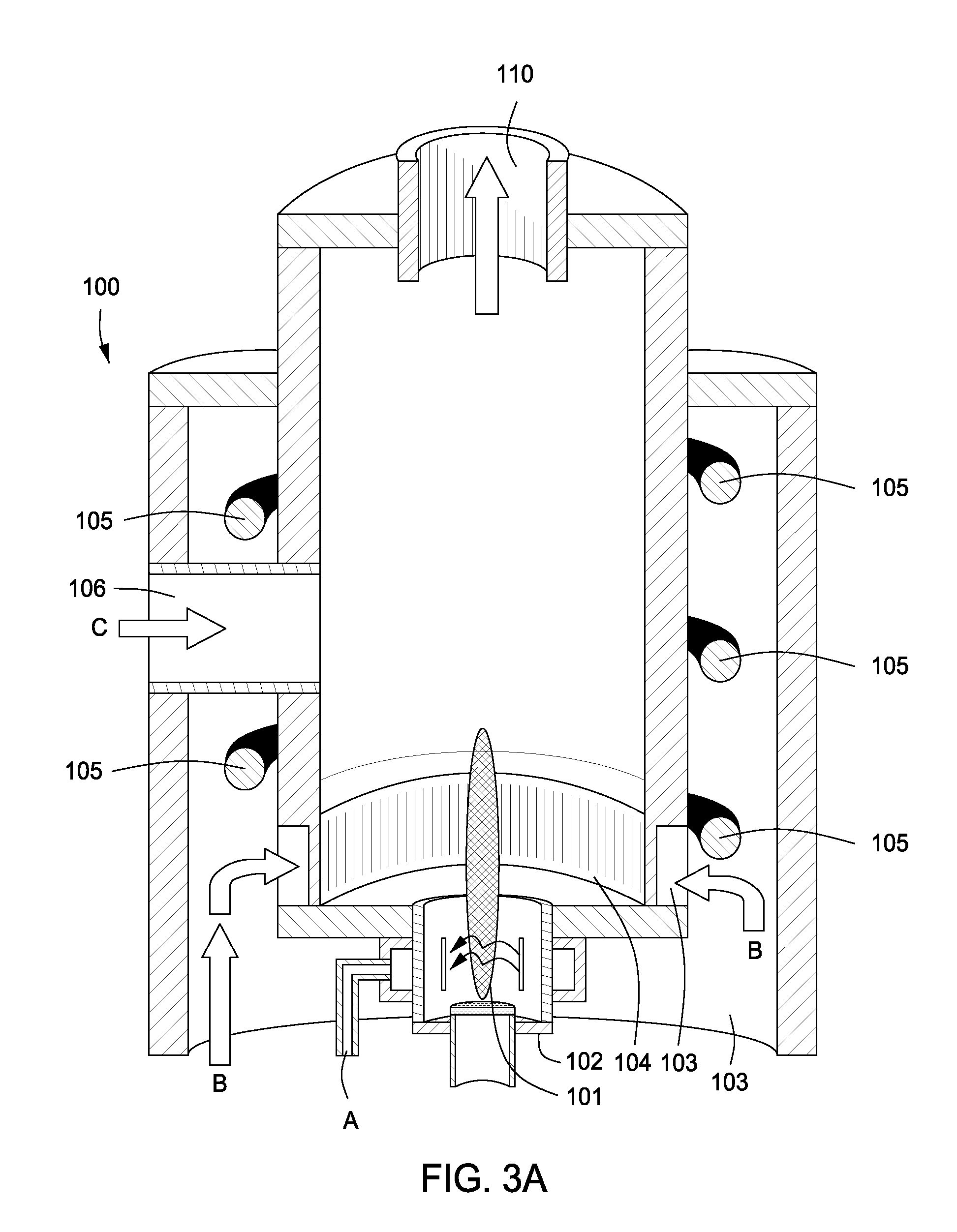
[0120]The present invention provides an apparatus for processing a material by using a vessel, wherein the vessel has (a) an interior defined by a cylindrical portion disposed between a first end and a second end, (b) an outlet in the first end that is aligned with a longitudinal axis of the cylindrical portion, (c) an inlet in the cylindrical portion to receive the material, (d) a first wave energy source comprising a first electrode disposed at least partially within the outlet and aligned with the longitudinal axis, and a second electrode disposed at least partially within the second end, aligned with the longitudinal axis and spaced apart from the first electrode, (e) a second wave energy source comprising a set of radio frequency coils or windings disposed around or within the cylindrical portion, and (f) two or more jets or slits within the cylindrical portion.
[0121]In addition, the present invention provides an apparatus for processing a material using a vessel, wherein the vessel has (a) an interior defined by a cylindrical portion disposed between a first end and a second end, (b) an outlet in the first end that is aligned with a longitudinal axis of the cylindrical portion, (c) an inlet in the first end to receive the material, (d) a first wave energy source comprising a first electrode disposed at least partially within the outlet and aligned with the longitudinal axis, and a second electrode disposed at least partially within the second end, aligned with the longitudinal axis and spaced apart from the first electrode, (e) a second wave energy source comprising a set of radio frequency coils or windings disposed around or within the cylindrical portion, and (f) two or more jets or slits within the cylindrical portion.
[0122]Moreover, the present invention provides an apparatus for processing a material using a vessel, wherein the vessel has (a) an interior defined by a cylindrical portion disposed between a first end and a cone shaped second end, (b) a first outlet in the first end t...

Problems solved by technology

The vented or flared gas is a wasted and untapped source of energy.
Particulate matter is of concern because very small particles may not be able to be filtered out by the respiratory system of a mammal.
The disposal of the separated shale and cuttings is a complex environmental problem.
Drill cuttings contain not only the mud product that can contaminate the environment, but also typically contain oil that is particularly hazardous to the environment, especially when drilling in a marine environment.
Unburned or unreacted carbon has plagued several other industries and / or processes, such as olefin plants in the petrochemical industry.
The petrochemical industry, as well as the refining industry, has been plagued with Volatile Organic Carbon (VOC) emission releases, as well as solid waste release problems.
A valuable resource is being wasted by flaring such a gas with the end product being carbon dioxide, a green house gas, with the potential for releasing toxic emissions.
In addition, with the new low-sulfur diesel regulations on the horizon, vast amounts of hydrogen will be required for hydro-treating processes used in refineries to reduce the heteroatom content of fuel products.
Many oil and gas companies are finding it uneconomical to fund conventional process units utilizing steel and concrete.
The downside of the SAR combustion process is that the oxygen used for combustion must be fed to the furnace very precisely in order to achieve proper combustion while limiting the amount of air in the stream.
Regeneration of spent sulfuric acid is two to three times as expensive as acid made directly made from sulfur.
The disposal of spent sulfuric acid is an ever increasing problem because of environmental regulations that are becoming more and more stringent.
The combustion that is normally carried out with air, which contains 21% oxygen with the remainder being nitrogen, puts nitrogen into the process, which plays no useful role in the waste combustion but leads to heat losses in the stack and reacts with oxygen to produce nitrogen oxides (known as thermal NOx), which in turn leads to smog formation, ozone depletion in the atmosphere and acid rain.
The formation of thermal NOx is extremely temperature sensitive.
However, this approach has not been widely adopted in the market place because oxygen enrichment leads to an increase in the furnace flame temperature, including localized hot spots.
These hot spots have a detrimental effect on the materials of construction of the combustor and oxygen constitutes an additional cost of production that the regeneration facility has to incur.
While faced with the need to expand capacity, refineries are often limited by both physical space and environmental restraints from expanding capacity of these process units, for example, by the addition of furnaces or converters.
Many crudes are of very low quality due to sulfur contamination.
As previously stated, refineries will have to make dramatic and costly capital investments in order to process low quality crudes, such as those produced in Mexico and Venezuela.
Also, additional expenditures will be required for increased hydro-treating capacity in order to produce low sulfur distillates.
For example, animal feeding operations (AFO) produce large amounts of manure that runs off into local waterways creating a pollution problem.
Phosphorous in the animal waste has been linked to causing hypoxia in receiving waters.
Transportation costs for hauling these additives to the farm, or the animal waste to the site where the additive is produced, is cost prohibitive.
Many smelters in the BPA region had already closed their doors because high energy prices made aluminum production unprofitable.
BPA can only produce 8,000 megawatts.
The red mud is typically stockpiled on-site since, resulting in the accumulation of ever-increasing amounts of red mud at the plant site.
In combination with rising energy costs and environmental issues, the aluminum industry is in great need of technologies for producing clean fuel or energy while simultaneously producing a useful byproduct from red mud.
The major problem with such a process is that the process requires copious amounts of water.
Hence, since the vehicle contains organic fluids such as lubricants, antifreeze, motor oil and gasoline, an undesirable emulsion is formed with the water.
Another problem associated with organic fluids forming emulsions in the dense medium separation process is that the metals may be covered or coated with organic fluids.
This in itself presents a recycling problem.
Although the price of the metals is not affected, the metals recycling facility must take precautions due to the potential for emissions of the organic fluids.
This problem is more common with aluminum ingot manufacturing from aluminum turnings from machine shops and fabrication facilities.
This problem has plagued aluminum recycling facilities.
Likewise, the paint on aluminum cans present a problem when recycling aluminum cans.
In addition, the regulations will limit the amount of fluff that can be disposed of in a landfill.
There is hardly any part of life where electrical and electronic equipment are not used.
In combination with the constant development of new materials and chemicals having environmental effects, this leads to increasing problems at the waste stage.
The growth of WEEE is about three times higher than the growth of the average municipal waste.2. Because of their hazardous content, electrical and electronic equipment cause major environmental problems during the waste management phase if not properly pre-treated.
However, a drawback to diesel engines is its exhaust emissions.
Under heavy load conditions, when the air / fuel mixture is too rich, the burning of the hydrogen element of hydrocarbons (HC) predominates, resulting in an excess of the unburned carbon element.
The disposal or final depositary for radioactive wastes is a major problem from both financial and environmental concerns.
Former nuclear weapons production sites face even more significant problems with radioactive waste management.
Furthermore, combining the comminution stage, reaction stage and separation stage is completely atypical for plasma processes and apparatuses.
Moreover, the utilization of plasma to generate angular momentum for kinetic energy comminution and reaction means is distinctive and unobvious from traditional kinetic energy communition such as a jet mill.

Method used


Image

  • Apparatus for Treating a Substance with Wave Energy from Plasma and an Electrical Arc
  • Apparatus for Treating a Substance with Wave Energy from Plasma and an Electrical Arc
  • Apparatus for Treating a Substance with Wave Energy from Plasma and an Electrical Arc

Examples


seventh embodiment

[0309]FIG. 13 is a diagrammatic, cross-sectional side view of a seventh embodiment Plasma & Arc Whirl Reactor 1300. The Plasma & Arc Whirl Reactor 1300 includes a vessel having (a) an interior 1302 defined by a cylindrical portion 1304 disposed between a first end 1306 and a second end 1308, (b) an outlet 112 in the first end 1306 that is aligned with a longitudinal axis 1310 of the cylindrical portion 1304, (c) an inlet 106 in the cylindrical portion 1304 to receive the material C, (d) a first wave energy source comprising a first electrode 1312 disposed at least partially within the outlet 112 and aligned with the longitudinal axis 1310, and a second electrode 1314 disposed at least partially within the second end 1308, aligned with the longitudinal axis 1310 and spaced apart from the first electrode 1312, (e) a second wave energy source comprising a set of radio frequency coils or windings 105 disposed around or within the cylindrical portion 1304, and (f) two or more jets or sli...

eighth embodiment

[0318]FIG. 15 is a diagrammatic, cross-sectional side view of an eighth embodiment Plasma & Arc Mill Reactor 1500. The Plasma & Arc Mill Reactor 1500 includes a vessel having (a) an interior 1302 defined by a cylindrical portion 1304 disposed between a first end 1306 and a second end 1308, (b) an outlet 112 in the first end 1306 that is aligned with a longitudinal axis 1310 of the cylindrical portion 1304, (c) an inlet 106 in the first end 1306 to receive the material C, (d) a first wave energy source comprising a first electrode 1312 disposed at least partially within the outlet 112 and aligned with the longitudinal axis 1310, and a second electrode 1314 disposed at least partially within the second end 1308, aligned with the longitudinal axis 1310 and spaced apart from the first electrode 1312, (e) a second wave energy source comprising a set of radio frequency coils or windings 105 disposed around or within the cylindrical portion 1304, and (f) two or more jets or slits 104 withi...

ninth embodiment

[0327]FIG. 16 is a diagrammatic, cross-sectional side view of a ninth embodiment Hyper Plasma & Arc Cyclone Separator Reactor 1600. The Hyper Plasma & Arc Cyclone Separator Reactor 1600 includes a vessel having (a) an interior 1302 defined by a cylindrical portion 1304 disposed between a first end 1306 and a cone shaped second end 1602, (b) a first outlet 112 in the first end 1306 that is aligned with a longitudinal axis 1310 of the cylindrical portion 1304, (c) a second outlet 1604 in the cone shaped second end 1602 that is aligned with the longitudinal axis 1310, (d) an inlet 106 in the first end 1306 to receive the material C, (e) a first wave energy source comprising a first electrode 1312 disposed at least partially within the first outlet 112 and aligned with the longitudinal axis 1310, and a second electrode 1314 disposed at least partially within the second outlet 1604, aligned with the longitudinal axis 1310 and spaced apart from the first electrode 1312, (f) a second wave ...


PUM


Abstract

An apparatus for synergistically combining a plasma with a comminution means such as a fluid kinetic energy mill (jet mill), preferably in a single reactor and / or in a single process step is provided by the present invention. Within the apparatus of the invention potential energy is converted into kinetic energy and subsequently into angular momentum by means of wave energy, for comminuting, reacting and separation of feed materials. Apparatuss of use of the apparatus in the practice of various processes are also provided by the present invention.

Description

CROSS REFERENCE TO RELATED APPLICATIONS[0001]This patent application is a continuation-in-part application of both U.S. patent application Ser. No. 12 / 577,166 filed on Oct. 10, 2009 and entitled “Plasma Whirl Reactor Apparatus and Apparatuss of Use” and U.S. patent application Ser. No. 12 / 949,736 filed on Nov. 18, 2010 and entitled “Apparatus for Treating Liquids with Wave Energy from an Electrical Arc.”[0002]U.S. patent application Ser. No. 12 / 577,166 is a continuation patent application of U.S. patent application Ser. No. 10 / 196,466 filed on Jul. 15, 2002 and entitled “Plasma Whirl Reactor Apparatus and Apparatuss of Use” which is a non-provisional patent application of U.S. provisional patent application 60 / 305,833 filed on Jul. 16, 2001. All of the foregoing patent applications are hereby incorporated by reference in their entirety.[0003]U.S. patent application Ser. No. 12 / 949,736 is a divisional application of U.S. patent application Ser. No. 11 / 784,326 filed on Apr. 5, 2007 an...

Claims


Application Information

Patent Timeline
IPC IPC(8): B09B3/00
CPCA23B4/015C02F2305/10A23L3/26B01J19/008B01J19/08B01J19/088B01J19/123B01J19/128B01J19/2405B01J19/247B01J2219/0809B01J2219/083B01J2219/0839B01J2219/0869B01J2219/0877B01J2219/0884B01J2219/185B01J2219/1946C02F1/30C02F1/302C02F1/32C02F1/36C02F1/4608C02F2103/008C02F2103/16C02F2103/22C02F2301/024C02F2301/026C02F2305/023A23L2/50Y02W10/37
Inventor FORET, TODD
Owner FORET PLASMA LABS
Learn More