Image acquisition apparatus including adaptive optics

an image acquisition and optics technology, applied in the field of image acquisition apparatus including adaptive optics, can solve the problems of reducing the time of image acquisition, limiting the energy that can be irradiated to prevent the damage of the retina of the eye, and unable to realize the increase of the light beam, etc., to achieve the effect of high definition of images

Inactive Publication Date: 2012-02-09
CANON KK
View PDF11 Cites 4 Cited by
  • Summary
  • Abstract
  • Description
  • Claims
  • Application Information

AI Technical Summary

Benefits of technology

[0023]According to the present invention, it is possible to realize an image acquisition apparatus including a compact adaptive optics that can realize hig

Problems solved by technology

However, the apparatus including the wavefront aberration correcting device by the single beam described above has a problem in attaining the reduction in image acquisition time instead the apparatus can attain the high definition of images.
However, if an object is a retina of an eye, energy that can be irradiated is limited to prevent the retina of

Method used


Image

  • Image acquisition apparatus including adaptive optics
  • Image acquisition apparatus including adaptive optics
  • Image acquisition apparatus including adaptive optics

Examples


example 1

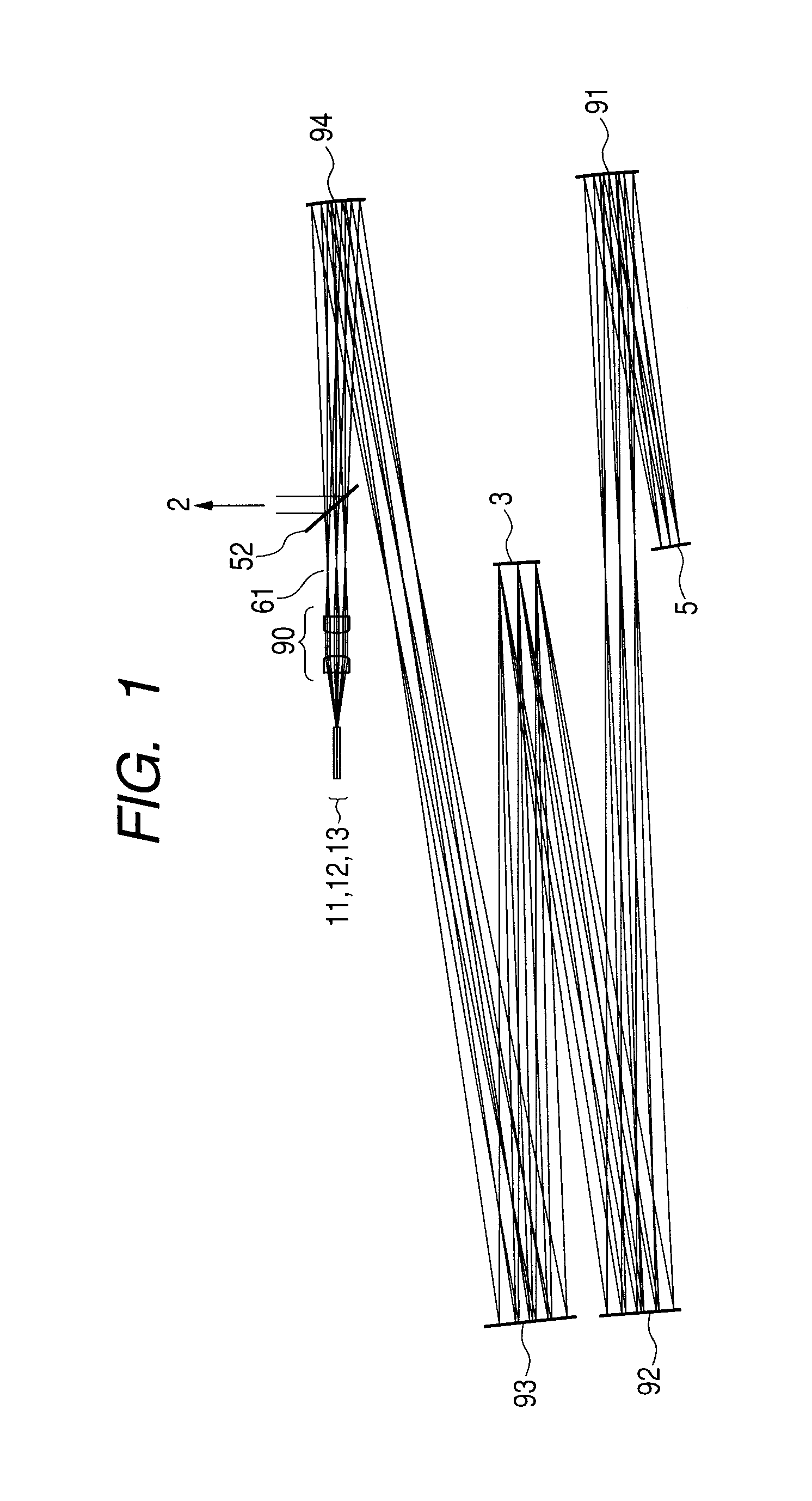
[0132]A main part of an image acquisition apparatus including an adaptive optics in Example 1 to which the present invention is applied is described using FIG. 1.

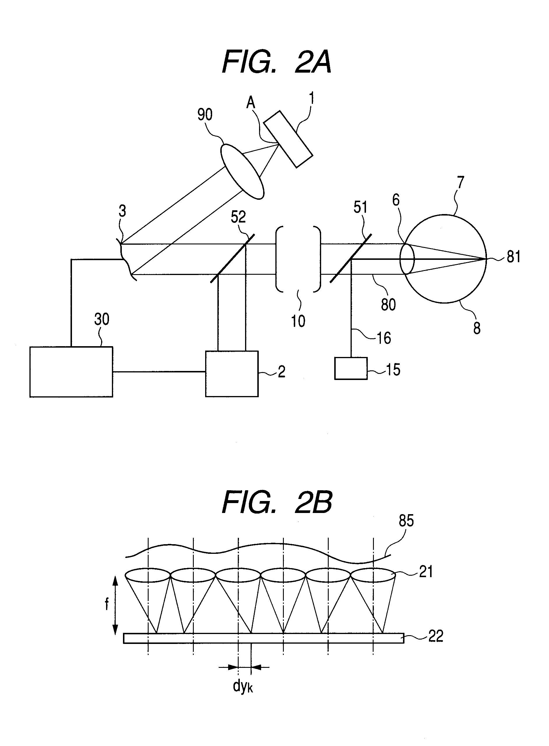
[0133]In FIG. 1, a wavefront aberration correcting device (DM) 3 and a beam emission ends 11, 12, and 13, which correspond to the fiber end A described in FIG. 2A, are provided.

[0134]A deflector 5, an exit pupil 61 of a collimator optical system, a collimator optical system 90, and aspherical mirrors aspherical mirror 91, 92, 93 and 94 are provided.

[0135]Light from a low-coherent light source for such as one of an SLO and an OCT propagates through three optical fibers. The light is emitted as divergent beams respectively from the emission ends 11, 12, and 13 arranged at a distance of 1 mm from one another in a decentered section (a paper surface) and collimated by the collimator optical system 90. A beam diameter (relative intensity 1 / e2) at this point is φ7.4 mm.

[0136]collimated three beams pass through the exit pupil 61. ...

example 2

[0151]Example 1 is an example in which the three beam emission ends are arranged in the decentered section (the yz surface). However, it is possible to simultaneously scan a larger number of beams and increase speed of image acquisition by arranging an emission end in the x axis direction as well.

[0152]Design data of an optical system in which nine (3×3) emission ends are arranged in a lattice shape on an xy surface is shown in Table 4. An angle of view x in a pupil is set to ±3 degrees in both x and y direction sections, a pupil diameter is set to φ6.7 mm, and wavelength is set to 840 nm. Wavefront aberrations of beams are illustrated in FIGS. 8A, 8B, 8C, 8D, 8E, and 8F. However, since the wavefront aberrations of the left line and the right line of FIG. 8G are symmetrical, characteristics of F3, F6, and F9 among angle of view positions illustrated in FIG. 8G are omitted. All the wavefront aberrations are around 0.9 in a Strehl ratio.

TABLE 4Surface NumberRadius of CurvatureSurface ...

example 3

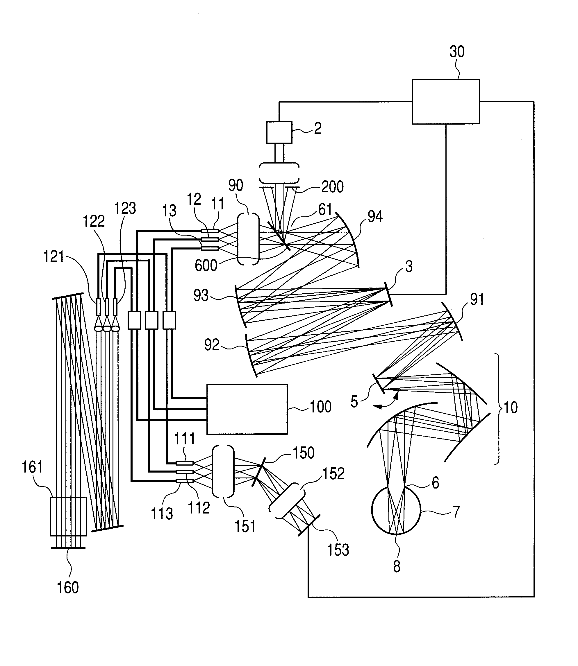
[0153]In Example 3, a configuration example in which the adaptive optics of the present invention described above is applied to an OCT capable of acquiring a three-dimensional tomographic image is described with reference to FIG. 9.

[0154]Light from a low-coherent light source 100 propagates through an optical fiber and is split at a predetermined ratio in a fiber coupler, then emitted as divergent beams respectively from the emission ends 11,12 and 13, and collimated by the collimator optical system 90.

[0155]Collimated three beams pass through the exit pupil 61. After passing through the exit pupil 61, the beams are made incident on the DM 3, which is a surface optically conjugate with the exit pupil 61 and the pupil 6 of the eye to be inspected, in a state of collimated beams at different angles by the aspherical mirrors 94 and 93 and superimposed on the DM 3 surface.

[0156]The diameter of the beams at this point is φ10 mm, which is slightly smaller than an effective diameter of the...


PUM


Abstract

An image forming apparatus including an adaptive optics realizing a reduction in image acquisition time and high definition without significantly increasing a light amount of a beam for scanning is provided, the apparatus including an adaptive optics scanning a plurality of areas in an object with a deflector using a measuring beam including a plurality of beams and corrects reflected and/or scattered beam from the object to acquire an image of the object, including: one or more wavefront aberration detecting device detecting wavefront aberration in each of the plurality of beams caused by the object when scanned by the measuring beam including the plurality of beams; and a single wavefront aberration correcting device correcting the wavefront aberration of each of the plurality of beams according to the detected wavefront aberration, the single wavefront aberration correcting device arranged in a position optically conjugate with the deflector.

Description

TECHNICAL FIELD[0001]The present invention relates to an image acquisition apparatus including an adaptive optics, and, more particularly to a technique for enabling acquisition of a two-dimensional image or a three-dimensional image at high resolution, concerning, for example, in vivo tissue such as a retina of an eye as an object.BACKGROUND ART[0002]As an image acquisition apparatus that performs acquisition of an image of in vivo tissue such as a retina of an eye as an object in a non-invasive manner, there are known an SLO (Scanning Laser Ophthalmoscope) capable of acquiring a two-dimensional image, an OCT (Optical Coherence Tomography) capable of picking up a tomographic image of an object, and the like. These apparatuses can scan a light beam on a retina using a deflector, measure reflected beam or scattered beam, and form two-dimensional images and three-dimensional images. At present, there is a demand for a further reduction in image acquisition time and higher definition o...

Claims


Application Information

Patent Timeline
IPC IPC(8): G01N21/55A61B3/10A61B3/103A61B3/12G01N21/17G02B17/08
CPCA61B3/1015A61B3/102A61B3/12G02B26/06G01J9/00G02B3/0056G02B17/0663A61B5/0062A61B5/0066
Inventor SAITO, KENICHI
Owner CANON KK
Why Eureka
Try Eureka