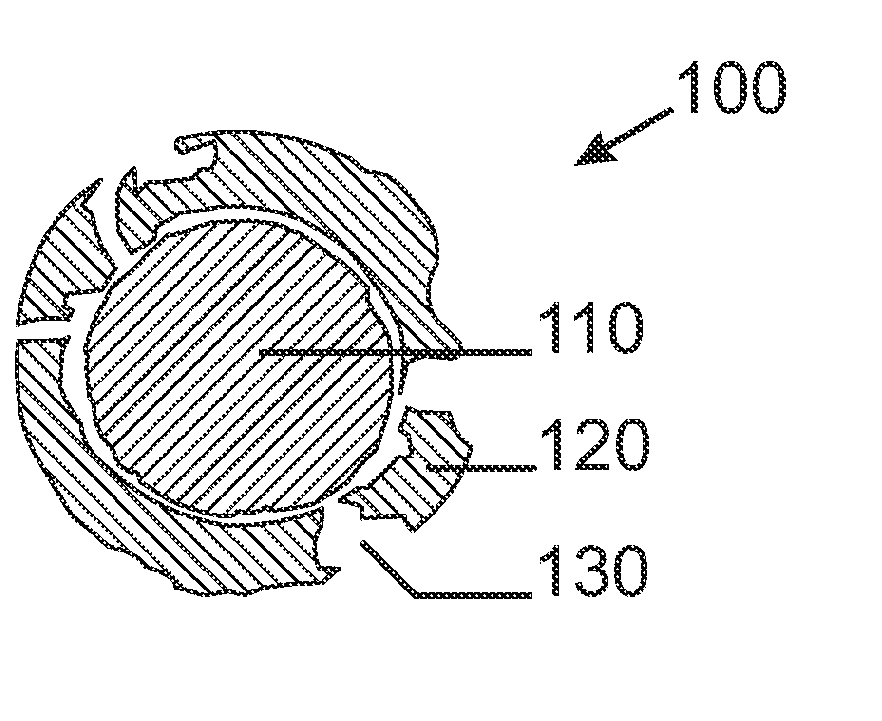
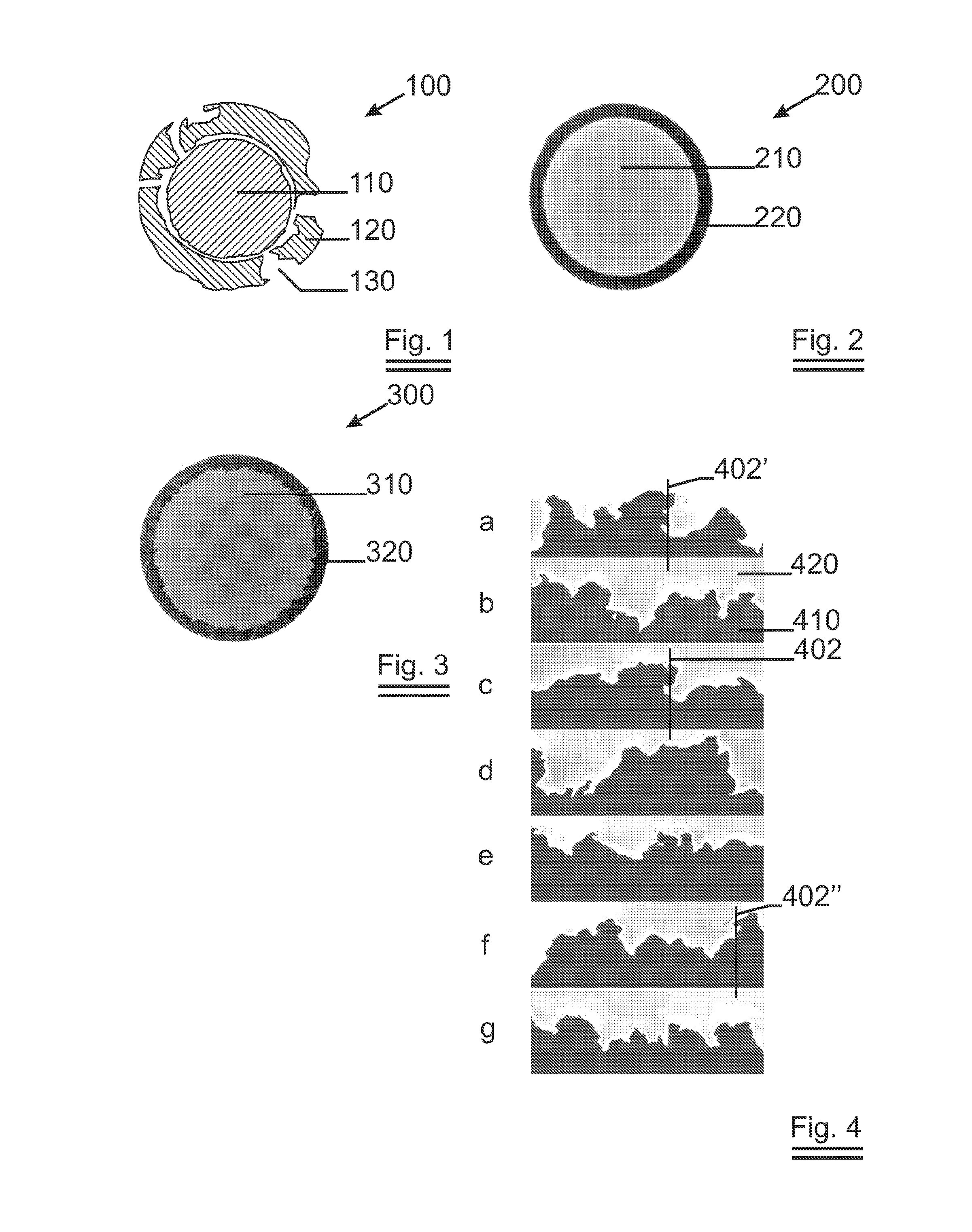
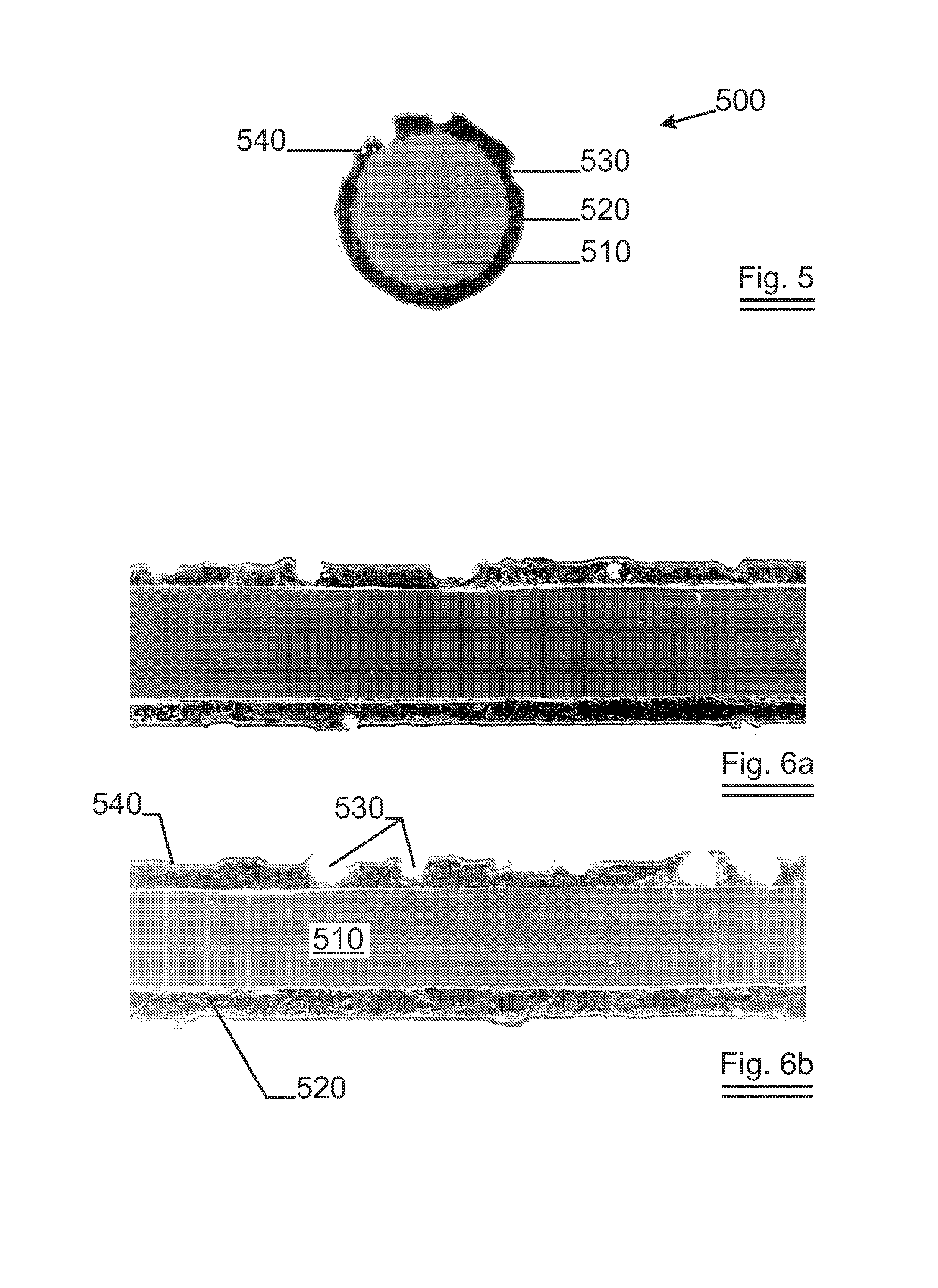
Fixed abrasive sawing wire with a rough interface between core and outer sheath

a technology of outer sheath, which is applied in the field of monofilament sawing wire, can solve the problems of inability to produce fixed abrasive sawing wires of an appreciable length, difficulty in holding resin particles during sawing, and low tensile strength of the resulting wire, so as to increase the lifetime of the sheath layer and ensure the smoothness of the sawing. the effect of ensuring the adheren

Inactive Publication Date: 2012-02-16
NV BEKAERT SA
View PDF18 Cites 26 Cited by
  • Summary
  • Abstract
  • Description
  • Claims
  • Application Information

AI Technical Summary

Benefits of technology

[0019]From the above it will be clear that the adherence of the sheath layer to the core must be improved such that the sheath layer does not release from the core during use. A well adhering sheath helps to increase t

Problems solved by technology

Although the ‘loose abrasive sawing’ is very much liked for its gentle sawing due to the ‘stick and rolling’ of the abrasive particles fed between workpiece and wire, it brings certain disadvantages with it in that:the wire wears in the process and must be replaced regularlythe slurry gets loaded with silicon swarf and metal debris while the abrasive particles lose their cutting ability and must be replaced regularly.
However, it is difficult to hold the particles in the resin during sawing.EP 0 243 825 describes a method to produce a fixed abrasive sawing wire starting from a steel wire rod and a tube surrounding the rod with a gap in between.
Drawbacks are that the method does not allow to produce fixed abrasive sawing wires of an appreciable length (above 100 meters), the tensile strength of the resulting

Method used


Image

  • Fixed abrasive sawing wire with a rough interface between core and outer sheath
  • Fixed abrasive sawing wire with a rough interface between core and outer sheath
  • Fixed abrasive sawing wire with a rough interface between core and outer sheath

Examples


third embodiment

[0098]In a second series of tests a second and third embodiment of the invention was produced starting from the same wire rod composition but with deviating diameters and coating thicknesses. The results of all date on final wires are summarised in Table 2 that also includes the results of the first sample.

TABLE 2DΔD′dNr(μm)(μm)(μm)(μm)δ (μm)d′ (μm)εδ / d′ (%)Ra (μm)Rt (μm)28806010001208.01363.985.90.896.491110099129817515.02053.687.31.128.7731100115133025025.03002.968.31.449.96

[0099]The results illustrate that an increased relative coating thickness results in a noticeable increased roughness. After indentation with the same type of diamonds and a nickel fixation layer the fixed abrasive sawing wire showed a similar cutting behaviour.

fourth embodiment

[0100]In a fourth embodiment, the wire of sample 1 was not coated with a nickel layer after mechanical diamond indentation, but with an organic coating layer. Therefore the wire was electrostatically coated with an epoxy powder EP 49.7-49.9 from SigmaKalon based on Bisphenol-A (BPA) with curing agent. Subsequently the wire was cured in a run-through oven at temperature of 180° C. for about 120 to 540 seconds. Again the wire was tested on a silicon crystal block (46.6 mm high×125 mm wide). The machine was operated in ‘constant bow mode’ set at 3°, the wire tension was kept constant at about 8 N, 30 m of wire was cycled (thro and fro) in 7 seconds giving an average speed of (2×30 / 7=) about 8.6 m / s. Water with an additive was used as a coolant. The wire cut the crystal at a rate of 0.8 mm to 1.0 mm / min over the 125 mm width. The crystal was cut in about 42 minutes. Again no delamination was observed after cutting the crystal.


PUM

PropertyMeasurementUnit
Fractionaaaaaaaaaa
Diameteraaaaaaaaaa
Fractionaaaaaaaaaa

Abstract

A fixed abrasive sawing wire is presented that comprises a core (310) and an outer sheath layer (320) that is softer than the core. In the sheath abrasive particles are embedded that are held by a binding layer. The bond between core and sheath is enhanced by making it rough. The arithmetical mean deviating roughness must at least be higher than 0.50 micron. Particularly preferred is when interlocking between the core and the sheath is introduced. Such interface roughness can be obtained by subjecting the wire to sufficient cold forming by wire drawing. Interlocking will occur at even higher degrees of cold forming. The binding layer can be a metallic binding layer or an organic binding layer.

Description

TECHNICAL FIELD[0001]The invention relates to a sawing wire, more specifically a monofilament sawing wire whereon abrasive particles are fixed by a metallic fixing layer in a metallic sheath that surrounds a metallic core. The sheath of the wire is anchored to the core through an interface with a roughness. Such wires can be used for cutting hard and brittle materials like quartz (for e.g. quartz oscillators or mask blancs), silicon (for e.g. integrated circuit wafers or solar cells), gallium arsenide (for high frequency circuitry), silicon carbide or sapphire (e.g. for blue led substrates), rare earth magnetic alloys (e.g. for recording heads) or even natural or artificial stone.BACKGROUND ART[0002]Plain carbon steel sawing wires are widely used to cut for example silicon ingots into slices—called wafers—for use in semiconductor devices or for photovoltaic cells. Although the wire used is called a ‘sawing wire’ it are actually abrasive particles fed to the wire in a viscous slurry—...

Claims


Application Information

Patent Timeline
IPC IPC(8): B23D61/18
CPCB23D61/185B23D61/18B24D3/06B28D1/08
Inventor CAMPOS, GLAUBERGOOSSENS, DAVY
Owner NV BEKAERT SA
Why Eureka
Try Eureka