
Method, system and apparatus for multi-level processing

a multi-level processor and multi-processor technology, applied in multi-programming arrangements, instruments, generating/distributing signals, etc., can solve the problems of slowing down of clock speed rate increase, single processor architecture cannot continue to effectively utilize these improvements, and the performance of single processors has started to reach their limit, so as to reduce the cost of synchronization overhead, reduce power consumption, and reduce the effect of synchronization waiting tim

Inactive Publication Date: 2012-04-19
CONVERSANT INTPROP MANAGEMENT INC
View PDF8 Cites 9 Cited by
  • Summary
  • Abstract
  • Description
  • Claims
  • Application Information

AI Technical Summary

Benefits of technology

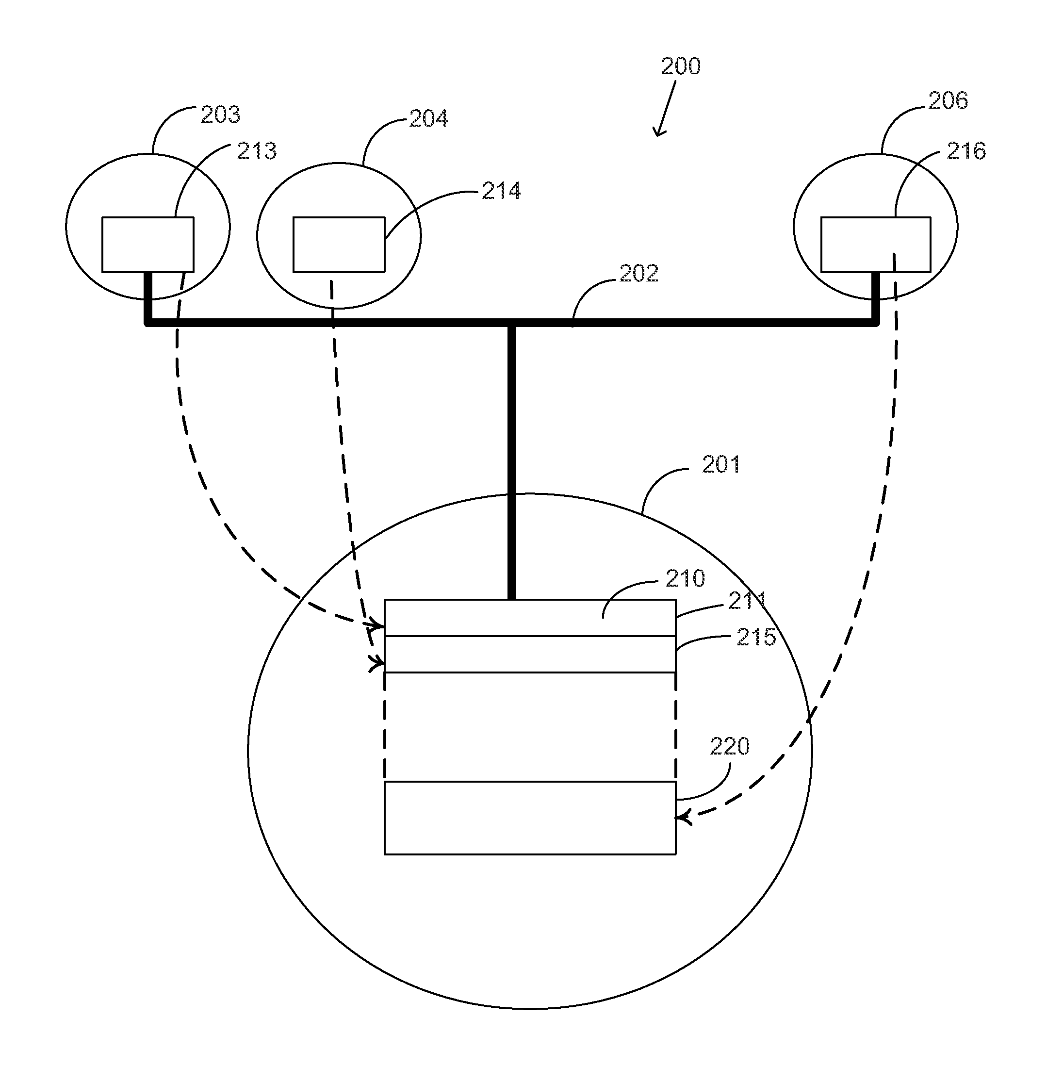
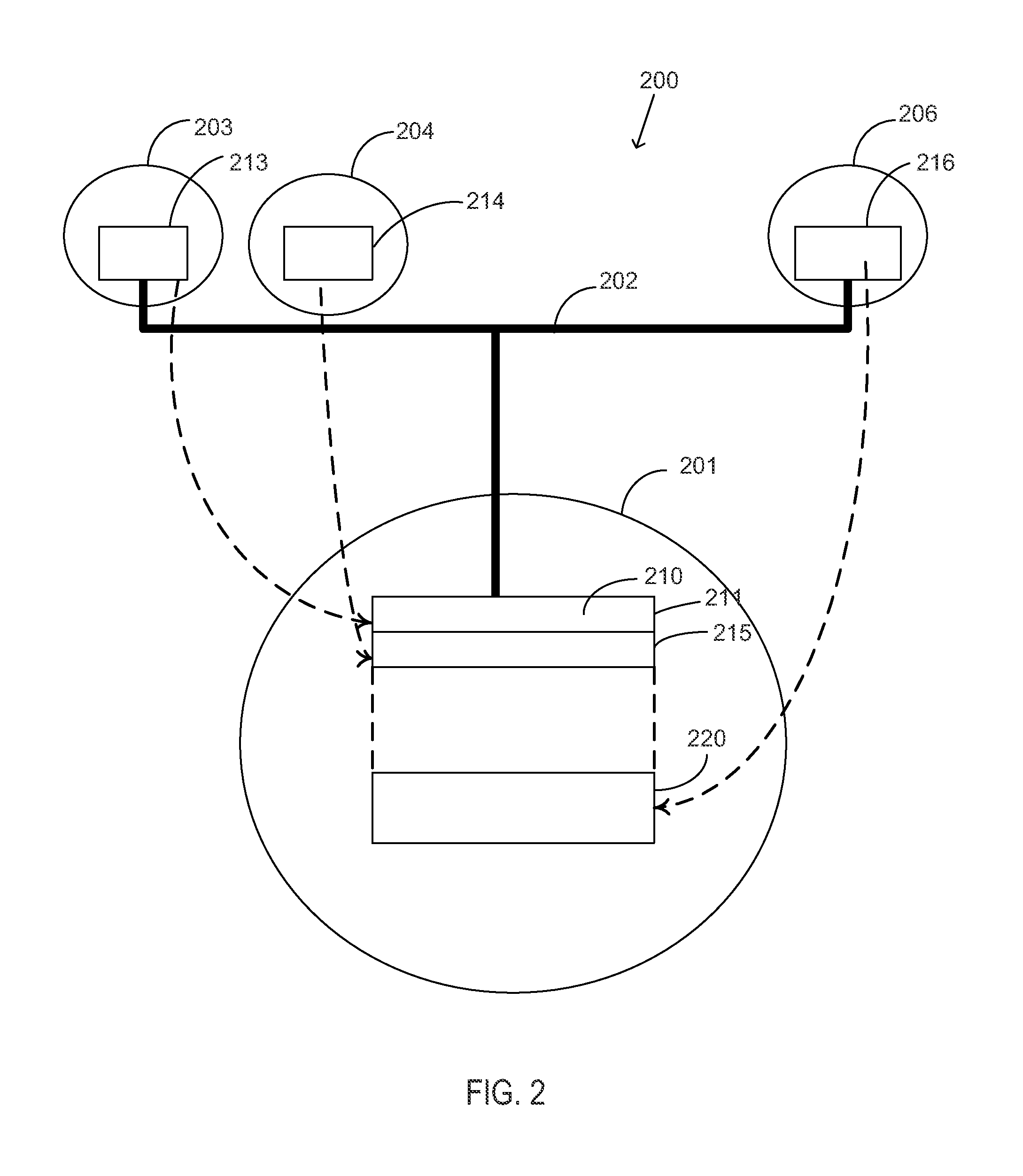
[0028]Multi-Level Processing as described herein reduces the cost of synchronization overhead by having an upper level processor take control and issue the right to use shared data or enter critical section directly to each processor at the processor speed without the need for each processor to be involved in synchronization. The instruction registers of lower level parallel processors are mapped to the upper level processor data memory without copying or transferring thus enabling the upper level processor to read each parallel processor's instruction and change it without any involvement or awareness from low level parallel processors. A system using Multi Level Processing as described reduces synchronization waiting time for a 32 conventional multiprocessor system using a 100 cycle bus from 32×32×100 cycle to only 32×1 cycle offering a gain of 3200 times. In addition, the system allows concurrent accessing of different shared data items and the ability to halt each processor to reduce power while waiting for the right to access shared data. The described embodiments offer an easy way to support vector operations using effective implementation to SIMD. The system makes parallel programming simpler for programmers by having a higher level processor generate parallel code from sequential code which reduces bandwidth requirements for instruction fetch. When lower level processors are used as synchronizing processors to yet another lower level parallel processors, the system will offer unlimited scalability for multiprocessors.

Problems solved by technology

The performance of single processor has started to reach its limit due to the growing memory / processor speed gap and a delay due to the conductors inside the chip.
This is combined with a slowdown in clock speed rate increase due to power and thermal management limitations brought about by higher component density.
Although technology is still improving, producing more transistors per chip at higher speed the architecture of single processor cannot continue to effectively utilize these improvements.
The performance gain of multiprocessor systems is also limited by fundamental problems mainly due to synchronization and communication overheads.
Prior attempts to solve the synchronization problem have had limited success.
The speedup of a program using multiple processors in parallel computing is limited by the time needed for the sequential fraction of the program.
While waiting, the processors spin in a tight loop wasting time and power.
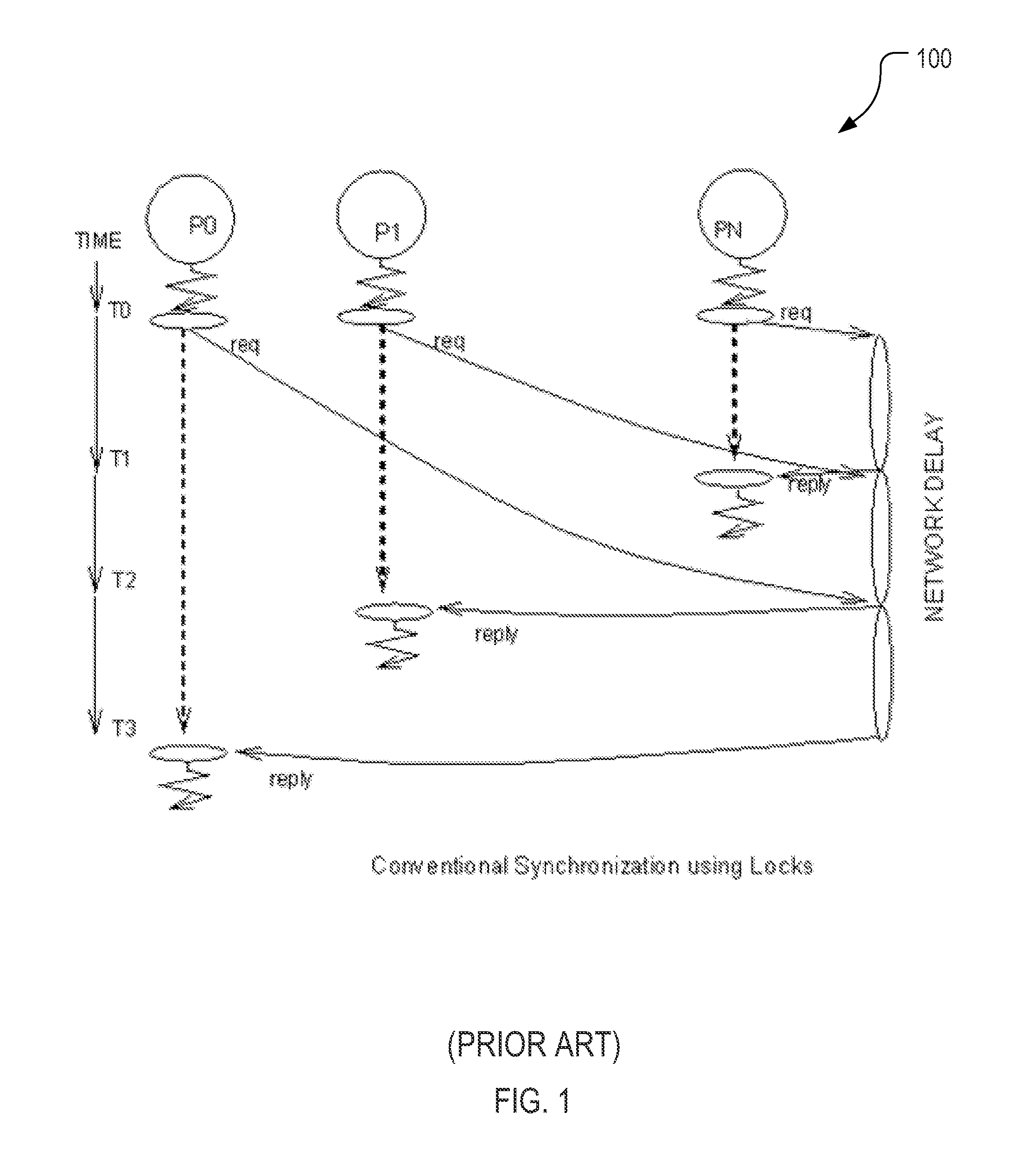
The time cost of synchronization for a 32-processor in SGI Origin 3000 system is that it takes 232,000 cycles during which the 32 processors could have executed 22 million FLOPS and which is a clear indication that conventional synchronization hurt system performance.
Any reference to the block from another processor between the LL and SC pair causes the SC to fail.
The synchronization cost for this is a latency of using the bus or network plus each time a processor fails, it must use the bus to load the block from the cache (because of the invalidation) repeatedly while spinning around in a tight loop waiting for a successful SC and wasting time and power.
A problem with this method is that it emulates the large scale multiprocessor system but does not accurately represent its behavior.
For example, when RAMP uses real processors, then processor memory speed ratio becomes very large, causing limitations to performance gain of huge number of processors and needs to hide the large latency of memory gap.
Therefore it cannot be used for a real large scale parallel processing system.
If the transaction fails, it will not commit and overhead of supporting it is wasted.
A key challenge with transactional memory systems is reducing the overheads of enforcing the atomicity, consistency, and isolation properties.
Hardware TM limitations are due to hardware buffering forcing the system into a spill state in lower levels of memory hierarchy.
Software TM have additional limitations when caused to manipulate metadata to track read and write sets, the additional instructions, when executed increase the overhead in memory system and power consumption.
TM restricts a large chunk of code to run in parallel and depends on having concurrency among transactions, thus preventing fine grain parallelism, making system performance limited to performance of slowest transaction.
This method requires additional overhead to send and receive messages from each processor to the large core processor.
This method can only run the code of one critical section at a time in serial fashion, and cannot allow multiple concurrent groups of processors to run in their critical sections even if they are different.
A limitation is the larger processor consumes more power and costs more in terms of silicon to implement.
Another limitation in ACM is that when all other processors use the large processor to execute their serial code, the cache of the large processor stores codes and data from different program areas that lack spatial localities, causing an increase in cache miss rate due to evictions.

Method used


Image

  • Method, system and apparatus for multi-level processing
  • Method, system and apparatus for multi-level processing
  • Method, system and apparatus for multi-level processing

Examples


Embodiment Construction

[0043]The following embodiments are focused on dealing with the fundamental problems of parallel processing including synchronization. It is desirable to have a solution that is suitable for current and future large scale parallel systems. The embodiments eliminate the need for locks and provide synchronization through the upper level processor. The upper level processor takes control of issuing the right to use shared data or enter critical section directly to each processor at the processor speed without the need for each processor to compete for one lock. The overhead of synchronization is reduced to one clock for the right to use shared data. Conventional synchronization with locks cost N2 bus cycles compared to N processor cycles in the multi-level processing of the present invention. For a 32 conventional multiprocessor system using a 100 cycle bus, synchronization costs 32×32×100 cycle compared to only 32×1 cycle for multi-level processing offering a gain of 3200 times.

[0044]...


PUM


Abstract

A Multi-Level Processor 200 for reducing the cost of synchronization overhead including an upper level processor 201 for taking control and issuing the right to use shared data and to enter critical sections directly to each of a plurality of lower level processors 202, 203 . . . 20n at processor speed. In one embodiment the instruction registers of lower level parallel processors are mapped to the data memory of upper level processor 201. Another embodiment 1300 incorporates three levels of processors. The method includes mapping the instructions of lower level processors into the memory of an upper level processor and controlling the operation of lower level processors. A variant of the method and apparatus facilitates the execution of Single Instruction Multiple Data (SIMD) and single to multiple instruction and multiple data (SI>MIMD). The processor includes the ability to stretch the clock frequency to reduce power consumption.

Description

FIELD OF THE INVENTION [0001]The present invention relates to computer data processing and in particular to a multi-processor data processing. With still greater particularity the invention relates to apparatus, methods, and systems for synchronizing multi-level processors.BACKGROUND OF THE INVENTION [0002]The power of a single microprocessor has seen continued growth in capacity, speed and complexity due to improvements in technology and architectures until recently. This improvement has of late reached a diminishing return. The performance of single processor has started to reach its limit due to the growing memory / processor speed gap and a delay due to the conductors inside the chip. This is combined with a slowdown in clock speed rate increase due to power and thermal management limitations brought about by higher component density.[0003]Although the performance of single processor is reaching its limit, the need for computing power is growing due to new multimedia applications,...

Claims


Application Information

Patent Timeline
Patent Type & Authority Applications(United States)
IPC IPC(8): G06F1/12G06F9/30G06F1/04
CPCG06F1/12G06F9/526G06F15/76G06F9/3887G06F9/30087G06F9/3851G06F9/3869G06F9/30079G06F9/3888G06F9/46G06F1/08G06F9/30G06F1/32
Inventor MEKHIEL, NAGI
Owner CONVERSANT INTPROP MANAGEMENT INC
Learn More