Thermal Power Plant

a technology of thermal power plant and main steam pipe, which is applied in the direction of machines/engines, lighting and heating apparatus, and flue gas purification components. it can solve the problems of increasing construction costs, reducing efficiency, and generating a large amount of carbon dioxide, so as to reduce construction costs and material costs, improve reliability, and reduce thermal elongation

Inactive Publication Date: 2012-05-03
MITSUBISHI HITACHIPOWER SYST LTD
View PDF6 Cites 11 Cited by
  • Summary
  • Abstract
  • Description
  • Claims
  • Application Information

AI Technical Summary

Benefits of technology

[0028]According to the present invention, a thermal power plant includes: a steam generator for generating steam by use of heat recovered from a boiler having a 2 pass structure in which a furnace and a rear heat recovery area are continuously arranged in parallel; and a generator for rotating steam turbines including at least a high-pressure turbine by use of generated steam to generate electricity. The high-pressure turbine of the steam turbines is arranged near the rear heat recovery area of the boiler. Accordingly, main steam pipes of the thermal power plant are shorte

Problems solved by technology

The thermal power plants can use many kinds of fuel, but have a lower efficiency and generate a larger amount of emission of carbon dioxide in comparison with gas turbine combined cycle generators.
However, materials of main steam pipes etc. of thermal power plants, the materials withstanding a high tempera

Method used


Image

  • Thermal Power Plant
  • Thermal Power Plant
  • Thermal Power Plant

Examples


embodiment 1

Basic Structure

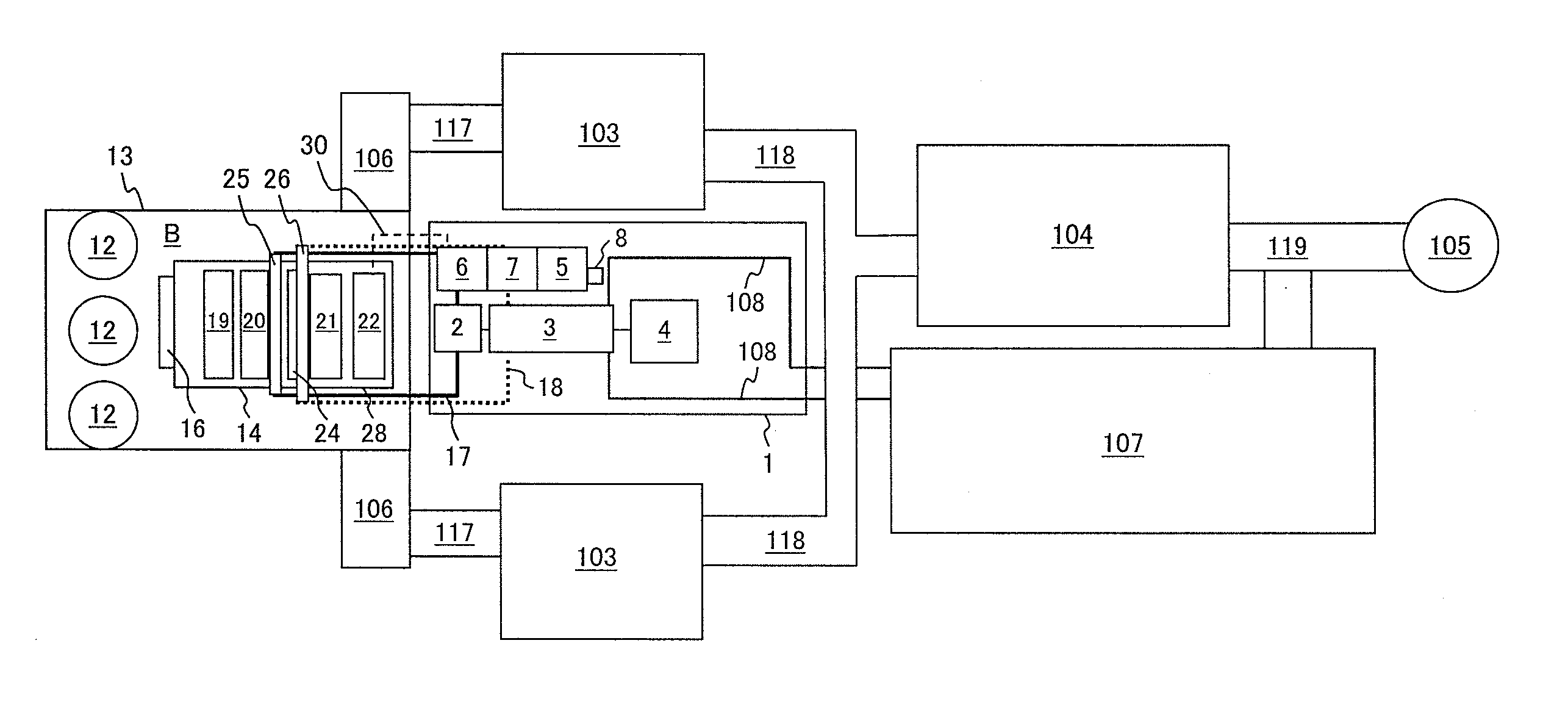
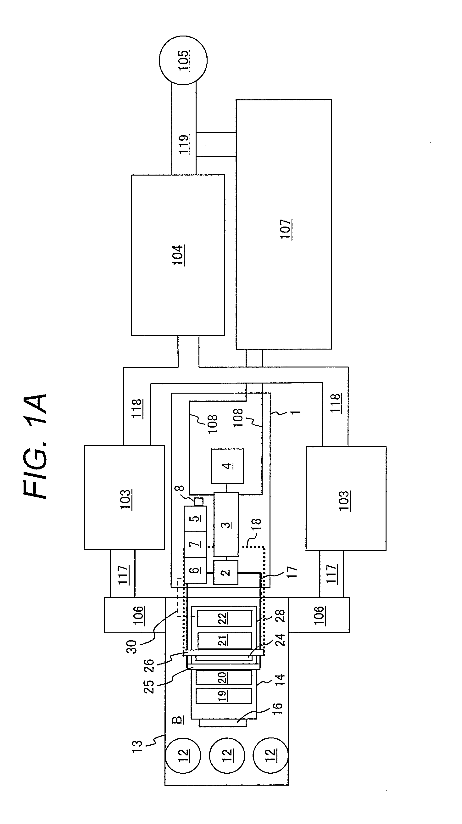
[0063]FIGS. 1A to 1C show arrangement of Embodiment 1 of a thermal power plant. A feature of Embodiment 1 is that a turbine building 1 is arranged on the side of an air quality control system (AQCS) of a boiler building 13. That is, a boiler B having a furnace 14 and a rear heat recovery area 28 are provided in the boiler building 13. The furnace 14, rear heat recovery area 28, and steam turbine building 1 are arranged in this order. Embodiment 1 shows the case where coal is used as fuel, and is applicable also to the case where oil, biomass, gas, petroleum coke, etc. are used.

[0064]Hereinafter, a combustion system and a flue gas treatment system are explained first, and next a water and steam system is explained.

Combustion System

[0065]First, in the combustion system, coal supplied to coal silos 12 is pulverized by a coal pulverizer 11, passes through coal supply lines (not shown), and is supplied from a burner 15 to the furnace 14. Air is drawn by a fan (not shown) i...

embodiment 2

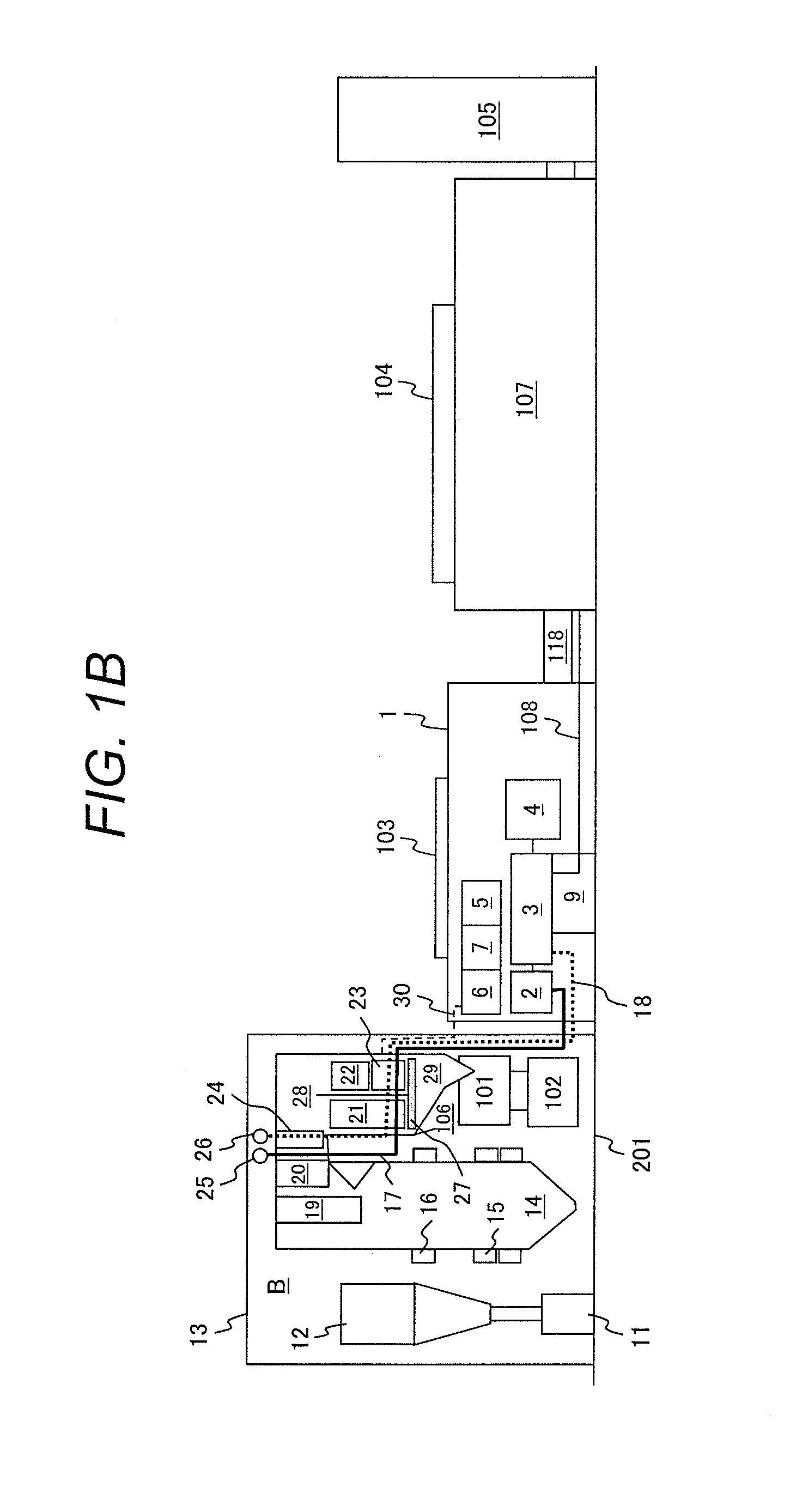
[0095]FIGS. 4A and 4B show Embodiment 2 of the present invention. In Embodiment 2, flue gas treatment systems such as the electrostatic precipitator 103 and the desulfurization apparatus 104 are arranged to one side of the boiler building 13 and one side of the turbine building 1. The advantages of this arrangement are as follows.

[0096](1) Since the turbine building is not surrounded by the flue gas treatment systems, the carrying-in of the apparatuses is easy.

[0097](2) The maintenance is easy because the flue gas treatment systems are gathered.

[0098](3) Since there is no communication duct 106 etc. in one side of the rear heat recovery area 28, the carrying of the apparatuses below the rear heat recovery area 28 is easy and an apparatus for removing ashes which accumulate in the ash hopper can be installed.

[0099]In this arrangement, the communication ducts 106 for drawing combustion gas from the rear heat recovery area 28 of the boiler B need to be installed on one side. Therefore,...

embodiment 3

[0101]FIGS. 5A and 5B show Embodiment 3 of the present invention. FIGS. 5A and 5B show the same structure as FIG. 4 except a position of the CO2 recovery apparatus 107. In using the chemical absorption method as the CO2 recovery apparatus 107, a large amount of steam is used. For this reason, when steam pipes are long, heat dissipation increases to decrease the efficiency of the plant. In Embodiment 3, lengths of steam supplying pipes 108 for the CO2 recovery apparatus are shortened by installing the CO2 recovery apparatus 107 next to the turbine building 1. Further, a predetermined space is provided between the turbine building and the CO2 recovery apparatus 107, and vehicles and equipment for the installation and repair are capable of entering this space.


PUM


Abstract

A thermal power plant is proposed for achieving high reliability, low material cost, and low construction cost by devising the arrangement and structures of a boiler, steam turbines, and a flue gas treatment apparatus to reduce a usage amount of high-temperature resistance material and further to reduce a thermal elongation of piping. In a thermal power plant including a 2 pass-type boiler having a furnace for burning fuel, a rear heat recovery area for recovering heat from combustion gas exhausted from the furnace, steam turbines are arranged near the rear heat recovery area.

Description

CLAIM OF PRIORITY[0001]The present application claims priority from Japanese patent application serial No. 2010-240209 filed on Oct. 27, 2010, the content of which is hereby incorporated by reference into this applicationBACKGROUND OF THE INVENTION[0002]1. Field of the Invention[0003]The present invention relates to a thermal power plant in which arrangement and structure of plant components are improved, and particularly to a thermal power plant including a 2 pass-type boiler having a low-rise structure in which a furnace and a rear heat recovery area are continuously arranged in parallel.[0004]2. Description of the Related Art[0005]Thermal power plants including a 2 pass-type boiler are widely used because these plants have a higher earthquake-resistance strength and can be constructed with lower cost in comparison with thermal power plants including a tower-type boiler. In the thermal power plants using a 2 pass type boiler, fuel and air are burned within a boiler, and water is h...

Claims


Application Information

Patent Timeline
IPC IPC(8): F01K13/00
CPCF22B37/24F01K13/00F01K11/02F22B37/008F22B37/40Y02E20/32
Inventor YAMAMOTO, KENJIHANDA, MASATONAGAFUCHI, NAOYUKIKUSUMI, NAOHIROFUKUDA, MITSUKOSHIBATA, TSUYOSHIMATSUURA, SHINJI
Owner MITSUBISHI HITACHIPOWER SYST LTD
Why Eureka
Try Eureka