Layered Emitter Coating Structure for Crack Resistance with PDAG Coatings

a technology of layered emitter and coating structure, applied in the direction of electrode construction, electrostatic separation details, lighting and heating apparatus, etc., can solve the problems of consuming power or other design problems, consuming power, and generally limited operating lifetime of devices, so as to reduce thermal solution footprint and volume, reduce vibration, and reduce power consumption

Inactive Publication Date: 2012-05-03
PANASONIC PRECISION DEVICES
View PDF6 Cites 7 Cited by
  • Summary
  • Abstract
  • Description
  • Claims
  • Application Information

AI Technical Summary

Benefits of technology

[0076]Advantages of use of an EHD device for thermal management in such devices includes, e.g., substantially silent operation, reduced power consumpti...

Problems solved by technology

It is known to provide cooling air flow with the use of fans or other similar moving mechanical devices; however, such devices generally have limited operating lifetimes, produce noise or vibration, consume power or suffer from other design problems.
Elevated ozone levels have been associated with respiratory irritation and certain health issues.
For example, EHD device performance reduction or failure can be caused by gradual coating of the emitter with silica.
Still other EHD devices produce unacceptable concentrations of ozone in the air transported through the device.
Additionally, some electrodes may be susceptible to oxidation, corona erosion, or accumulation of detrimental materials.
However, pure metals are often deficient in some regard with respect to other desirable materials characteristics.
While each of the elements present in the alloy will contribute in some way to the overall characteristics required, alloys of such metals do not always provide the same desirable characteristics as the pure metals would alone and such compound characteristics are not always readily predictable.
The alloy no longer contains either pure lead or pure tin so the beneficial effects of these elements may be altered, diminished or lost.
While some phases formed on alloying may present other beneficial materials characteristics, such beneficial properties are not readily determinable or predictable without extensive testing as the new phases do not present the same properties as the pu...

Method used


Image

  • Layered Emitter Coating Structure for Crack Resistance with PDAG Coatings
  • Layered Emitter Coating Structure for Crack Resistance with PDAG Coatings
  • Layered Emitter Coating Structure for Crack Resistance with PDAG Coatings

Examples


Embodiment Construction

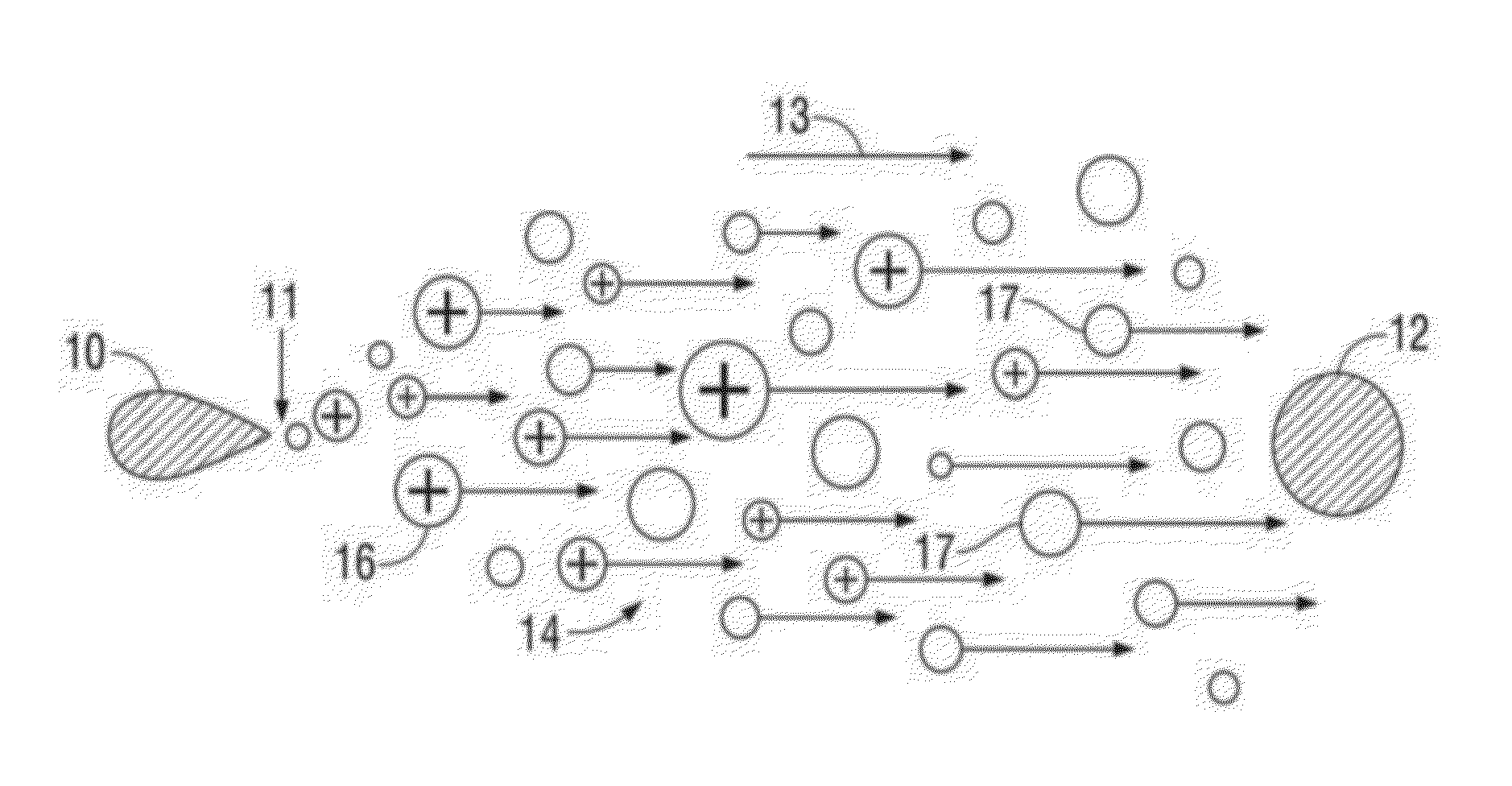
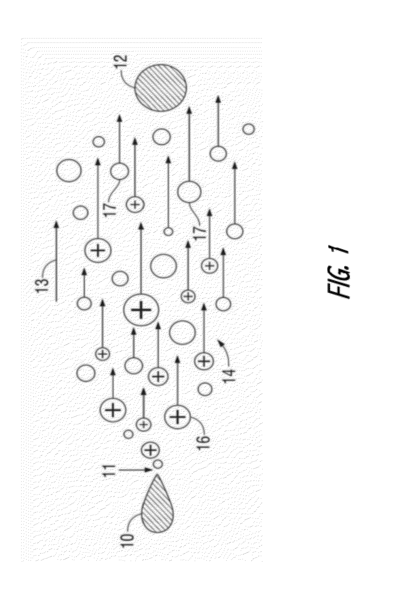
[0090]Some implementations of thermal management systems described herein employ EHD devices to motivate flow of a fluid, typically air, based on acceleration of ions generated as a result of corona discharge. Other implementations may employ other ion generation and motivation techniques and will nonetheless be understood in the descriptive context provided herein. For example, in some implementations, techniques such as silent discharge, AC discharge, dielectric barrier discharge (DBD) or the like may be used to generate ions that are in turn accelerated in the presence of electrical fields to motivate fluid flow.

[0091]Typically, when a thermal management system is integrated into an operational environment, heat transfer paths (often implemented as heat pipes or using other technologies) are provided to transfer heat from where it is generated or dissipated to a location(s) within an enclosure where air flow motivated by an EHD device(s) flows over primary heat transfer surfaces....


PUM


Abstract

A thermal management apparatus includes an electrohydrodynamic fluid accelerator in which an emitter electrode and another electrode are energizable to motivate fluid flow. The emitter electrode is a layered structure including an electrode core material and an outermost coating that is susceptible to micro-cracking or corona erosion. A barrier material is provided in a sublayer to protect the underlying electrode core material. An adhesion promoting layer may be used between the barrier material and the electrode core material or between other layers of the structure. solid solution. A method of making an EHD product includes positioning the layered electrode relative to another electrode to motivate fluid flow when energized.

Description

BACKGROUND[0001]1. Field of the Invention[0002]This application relates generally to electrodes in electrohydrodynamic or electrostatic devices such as electrohydrodynamic fluid accelerators and electrostatic precipitators, and particularly to classes of materials that can be used to form such electrodes.[0003]2. Description of the Related Art[0004]Many electronic devices and mechanically operated devices require air flow to help cool certain operating systems by convection. Cooling helps prevent device overheating and improves long term reliability. It is known to provide cooling air flow with the use of fans or other similar moving mechanical devices; however, such devices generally have limited operating lifetimes, produce noise or vibration, consume power or suffer from other design problems.[0005]The use of an ion flow air mover device, such as an electrohydrodynamic (EHD) device or electro-fluid dynamic (EFD) device, may result in improved cooling efficiency, reduced vibration...

Claims


Application Information

Patent Timeline
IPC IPC(8): F28F27/00
CPCB03C3/60
Inventor JEWELL-LARSEN, NELSGAO, GUILIAN
Owner PANASONIC PRECISION DEVICES
Why Eureka
Try Eureka