Thermally assisted magnetic random access memory element with improved endurance

a memory element and random access technology, applied in the field of magnetic random access memory elements, can solve the problems of limited capacity, limited integration possibility, and inability to guarantee the stability of the free layer magnetization with respect to heat fluctuations, so as to reduce the risk of tunnel barrier breakdown and aging, reduce induced stress, and reduce the effect of aging effects

Active Publication Date: 2012-05-03
CROCUS TECHNOLOGY
View PDF5 Cites 13 Cited by
  • Summary
  • Abstract
  • Description
  • Claims
  • Application Information

AI Technical Summary

Benefits of technology

[0038]The magnetic tunnel junction disclosed herein has a reduced induced stress during the writing operation and experience reduced aging effects since a lower voltage is applied across the tunnel barrier when the heating element is included in the magnetic tunnel junction. The inventive magnetic tunnel junction allows for passing a current having a high magnitude through the magnetic tunnel junction while keeping the voltage across the tunnel barrier at a low value. The magnetic tunnel junction can thus be heated effectively minimizing possible risks of breakdown and aging of the tunnel barrier. The lower voltage across the tunnel barrier reduces oxide stress and increase endurance of the magnetic tunnel junction during the different write operations.

Problems solved by technology

This technology, thanks to its architecture, enables non-volatile memories to be made with a simple technology, albeit of limited capacity.
The fact that the memory elements or points are connected serially along each line limits the possibility of integration, since the signal gets weaker and weaker as the number of memory elements or points increases.
As the distribution function of the switching fields for all of the memory points is wide (it is indeed not uniform because of manufacturing constraints and intrinsic statistical fluctuations), it is necessary that the magnetic field on the selected memory point be greater than the highest distribution switching field, with the risk of accidentally reversing certain memory points located on the corresponding line or column, where the switching field located in the lower part of the distribution is weaker than the magnetic field generated by the line or column alone.
Finally, the stability of the magnetization of the free layer with respect to heat fluctuations is no longer guaranteed when the size of the memory point diminishes.
By doing this, however, the magnetic field necessary for the magnetic switching increases, which results in an increased electric consumption for generating the field necessary to the magnetic switching.
The exposure of this thin oxide layer to repeating voltage cycling can lead to its degradation and hence limit the endurance of the TAS-MRAM cell.
Despite these advantages, there are however some difficulties in terms of manufacturing technology.
The main difficulty is linked to the need to apply a current pulse through the magnetic tunnel junction in order to heat the memory point to a temperature greater than the critical temperature of the antiferromagnetic layer pinning the storage layer.
This current pulse is liable to subject the ultra-thin oxide layer constituting the tunnel barrier to a considerable electric stress.
Furthermore, even if the voltage applied onto the tunnel barrier is lower than its breakdown voltage, the stress linked to the electric current pulse can result in considerable aging effects in the long term, notably after a great number of writing cycles.

Method used


Image

  • Thermally assisted magnetic random access memory element with improved endurance
  • Thermally assisted magnetic random access memory element with improved endurance
  • Thermally assisted magnetic random access memory element with improved endurance

Examples


Embodiment Construction

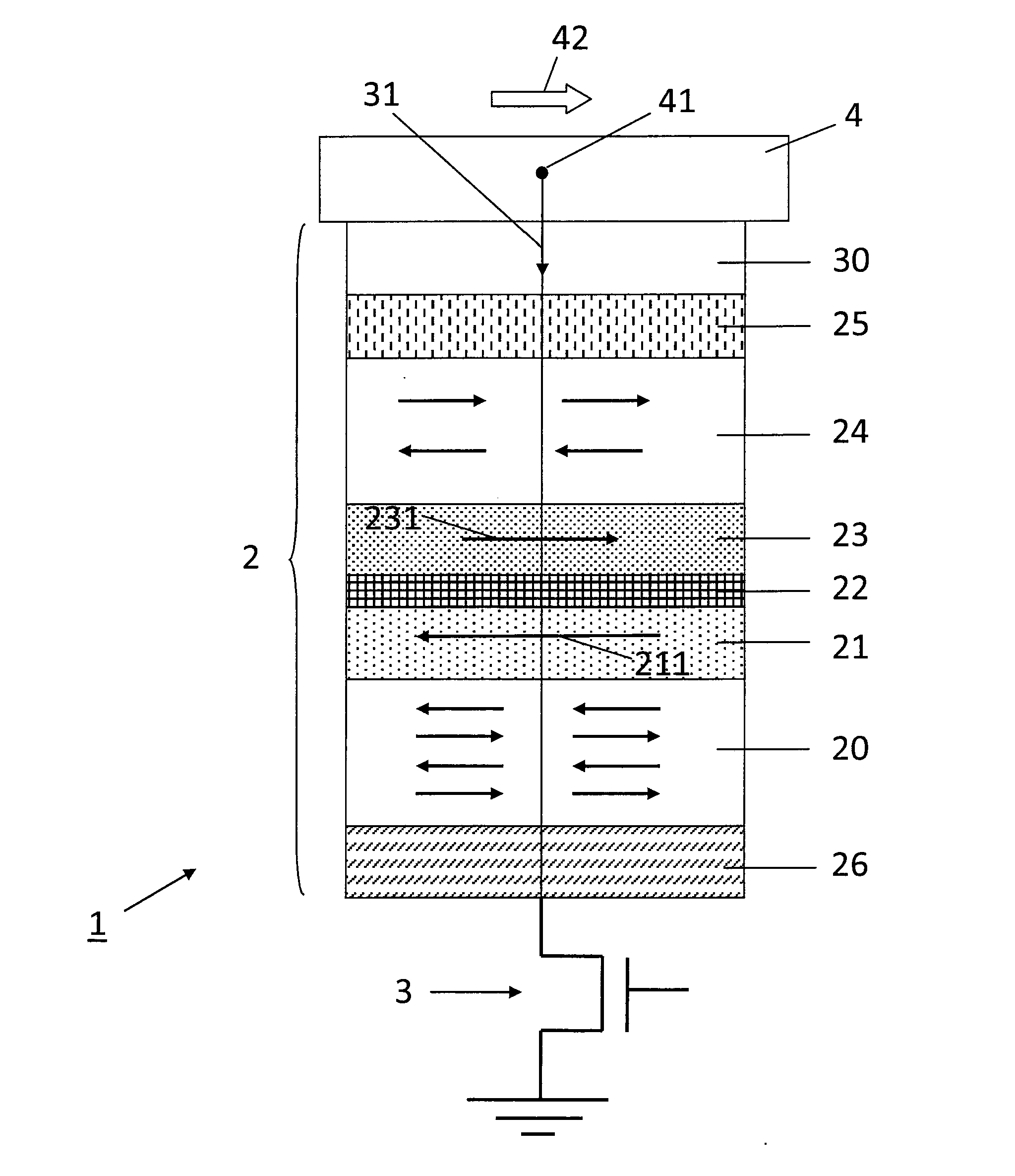
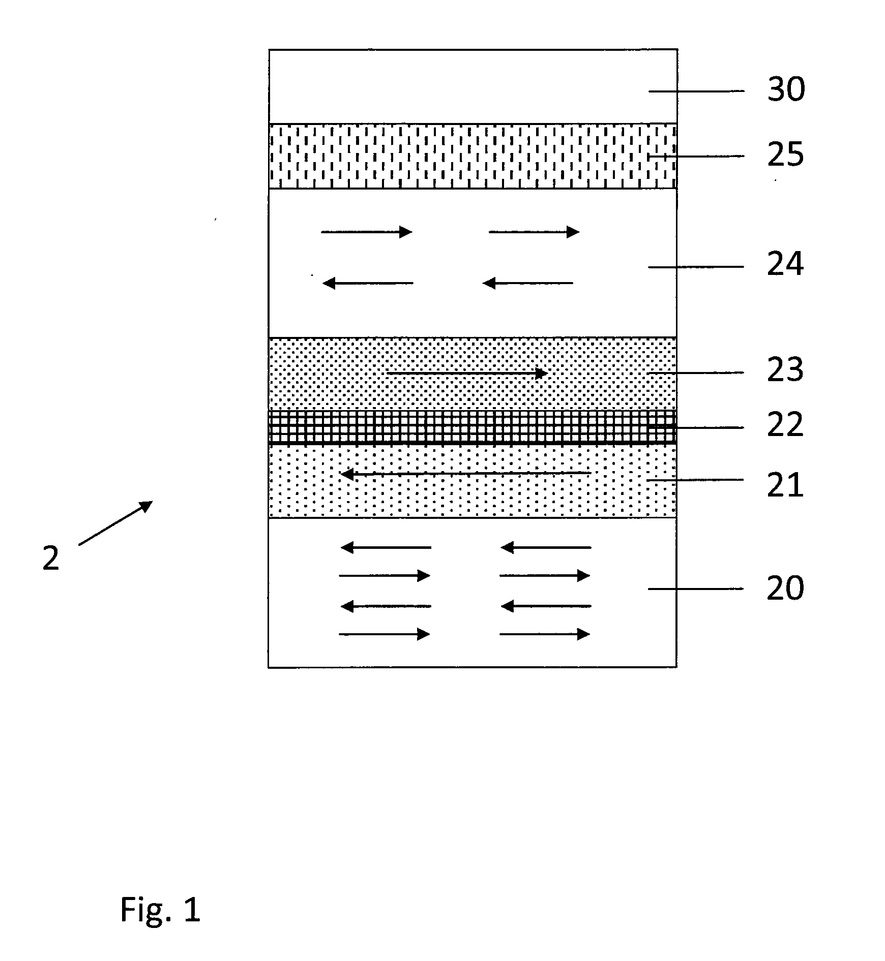
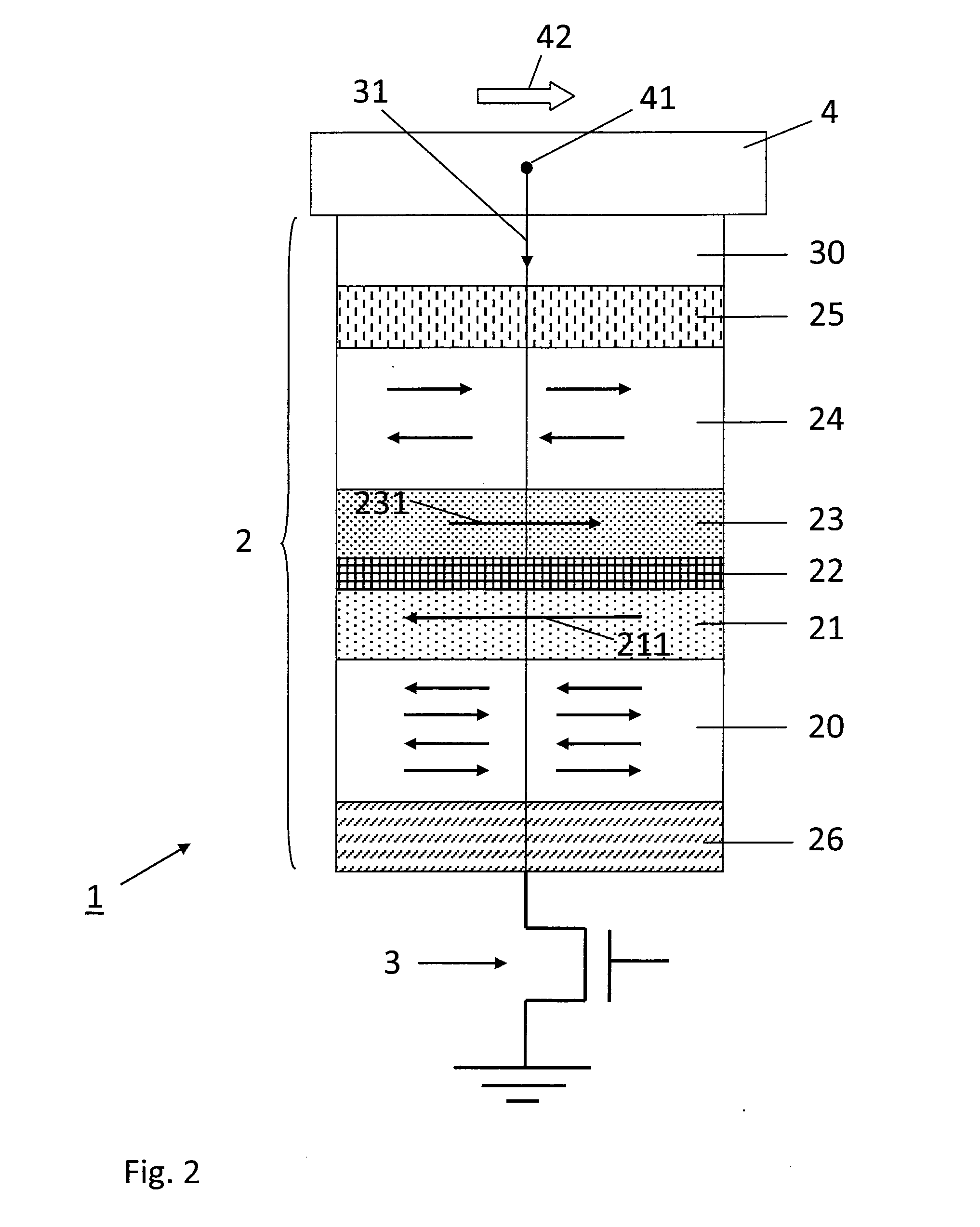
[0042]FIG. 1 illustrates a magnetic tunnel junction 2 according to an embodiment. The magnetic tunnel junction 2 comprises a first ferromagnetic layer, or reference layer 21, having a fixed magnetization; a second ferromagnetic layer, or storage magnetic layer 23, having a magnetization that can be freely aligned at a predetermined high temperature threshold; and a tunnel barrier 22 provided between the reference layer 21 and the storage layer 23. In the example of FIG. 1, the magnetic tunnel junction 2 comprises an antiferromagnetic storage layer 24, adjacent to the storage layer 23 and pinning the storage layer 23 at a predetermined low temperature threshold. At the predetermined high temperature threshold, the exchange coupling between the antiferromagnetic storage layer 24 and the storage layer 23 is reduced to zero and the magnetization of the storage layer 23 can be freely aligned. The reference layer21 can also be coupled by an antiferromagnetic reference layer 20 pinning its...


PUM


Abstract

The present disclosure concerns a magnetic memory element suitable for a thermally-assisted switching write operation, comprising a current line in electrical communication with one end of a magnetic tunnel junction, the magnetic tunnel junction comprising: a first ferromagnetic layer having a fixed magnetization; a second ferromagnetic layer having a magnetization that can be freely aligned at a predetermined high temperature threshold; and a tunnel barrier provided between the first and second ferromagnetic layer; the current line being adapted to pass a heating current through the magnetic tunnel junction during the write operation; wherein said magnetic tunnel junction further comprises at least one heating element being adapted to generate heat when the heating current is passed through the magnetic tunnel junction; and a thermal barrier in series with said at least one heating element, said thermal barrier being adapted to confine the heat generated by said at least one heating element within the magnetic tunnel junction.

Description

FIELD[0001]The present disclosure relates to a magnetic memory element with a thermally-assisted switching write operation comprising a magnetic tunnel junction and having an improved endurance to write operations. The present disclosure also pertains to a magnetic memory device comprising a plurality of the magnetic memory element.DESCRIPTION OF RELATED ART[0002]Magnetic elements with magnetic tunnel junction or spin valve, include those used in magnetic non-volatile random access memories (NVRAM), used for storing, reading and writing data in electronic systems in known ways. Magnetic MRAM memories have met with renewed interest following the development of magnetic tunnel junctions having a high magnetoresistance at ambient temperature. These MRAMs have indeed many advantages:[0003]a speed comparable with that of static random access memories (SRAM),[0004]non volatility, as in flash memories,[0005]absence of reading and writing degradation over time,[0006]insensitivity to ionizin...

Claims


Application Information

Patent Timeline
Patent Type & Authority Applications(United States)
IPC IPC(8): G11C11/15
CPCG11C11/16H01F10/3254H01F41/304H01L43/08B82Y40/00G11C11/1675H10N50/10
Inventor MACKAY, KENNETHPREJBEANU, IOAN LUCIAN
Owner CROCUS TECHNOLOGY
Why Eureka
Try Eureka