Hydrogen COGas For Carbon Implant

a carbon implant and hydrogen cogas technology, applied in the direction of ion beam tubes, vacuum evaporation coatings, coatings, etc., can solve the problems of reducing the efficiency of the ion source, poisoning the chamber, adding gas flow and pressure to the ion source without adding any usable precursor materials, etc., to facilitate the ion implantation process, reduce electron emission, beam current

Active Publication Date: 2012-05-17
AXCELIS TECHNOLOGIES
View PDF1 Cites 22 Cited by
  • Summary
  • Abstract
  • Description
  • Claims
  • Application Information

AI Technical Summary

Benefits of technology

[0010]Aspects of the invention facilitate ion implantation processes by removing oxygen atoms generated from the disassociation and ionization of carbon-containing source gases which can oxidize (poison) the ion source, thereby reducing electron emission from the cathode. Beam current, as well as lifetime of the ion source are thereby increased. Associated apparatus and an ion implantation system for carrying out the method are disclosed herein.

Problems solved by technology

The chamber 102 will react with the free oxygen ions to form tungsten and molybdenum oxides, which build up on these surfaces and detrimentally affect the efficiency of the ion source and poison the chamber 102.
A co-gas such as phosphine, however, adds gas flow and pressure to the ion source without adding any usable precursor material, as well as being more expensive and toxic than other alternatives.

Method used


Image

  • Hydrogen COGas For Carbon Implant
  • Hydrogen COGas For Carbon Implant
  • Hydrogen COGas For Carbon Implant

Examples


Embodiment Construction

[0019]The invention will now be described with reference to the attached drawings, wherein like reference numerals are used to refer to like elements throughout. It will be appreciated by those skilled in the art that the invention is not limited to the exemplary implementations and aspects illustrated and described hereinafter.

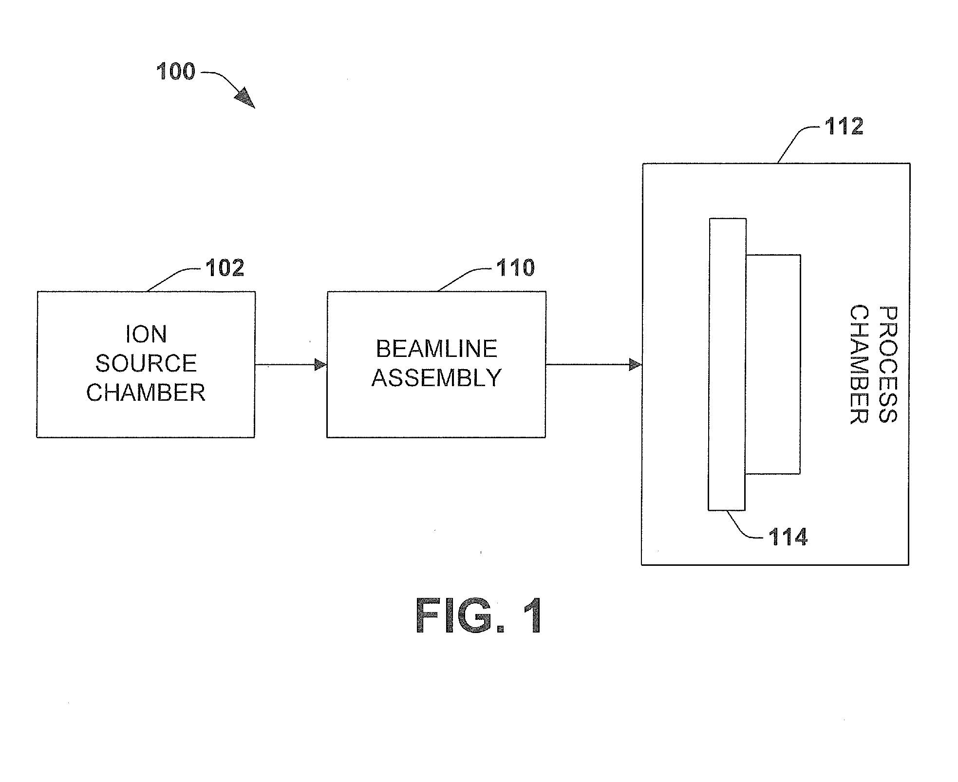
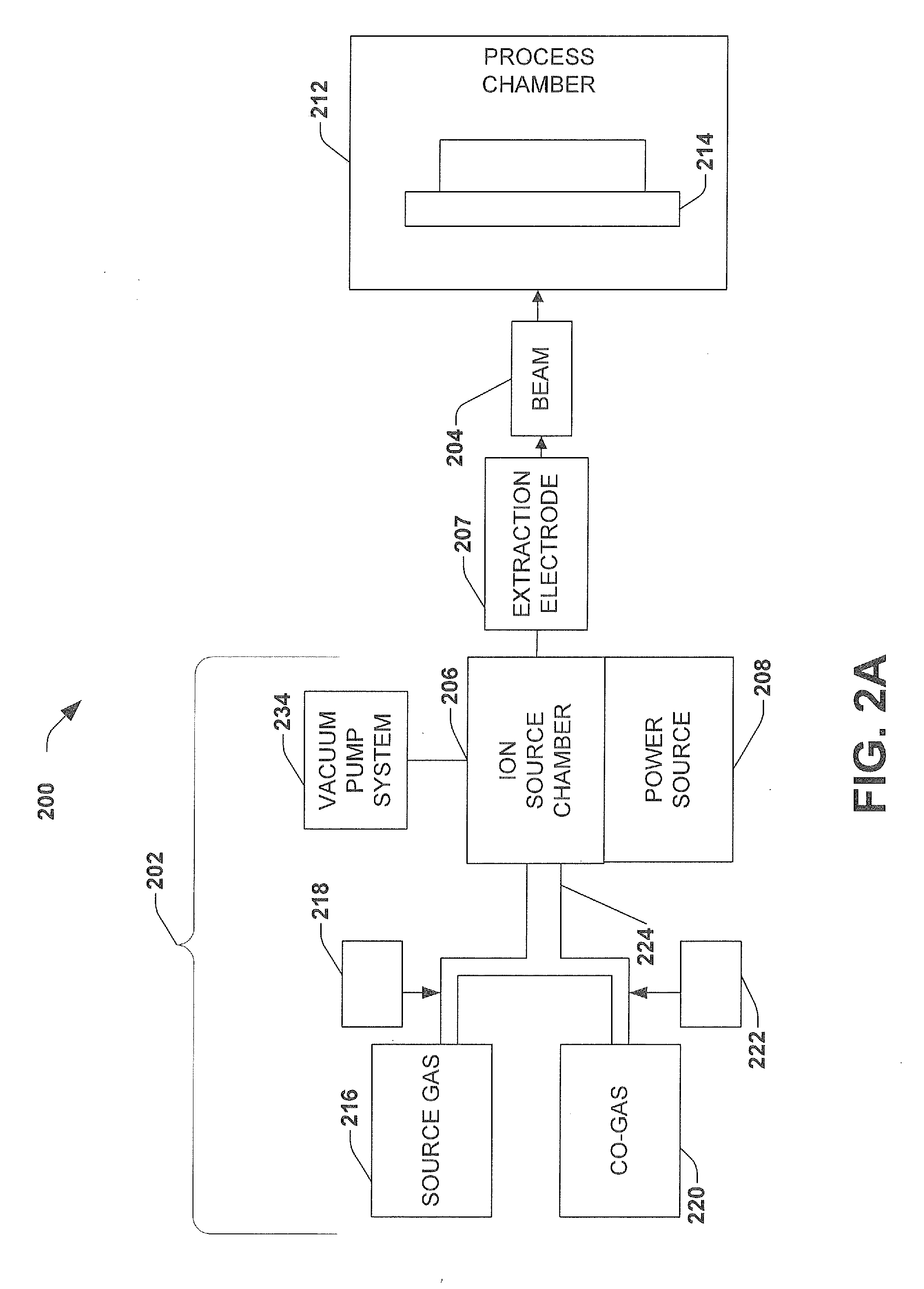
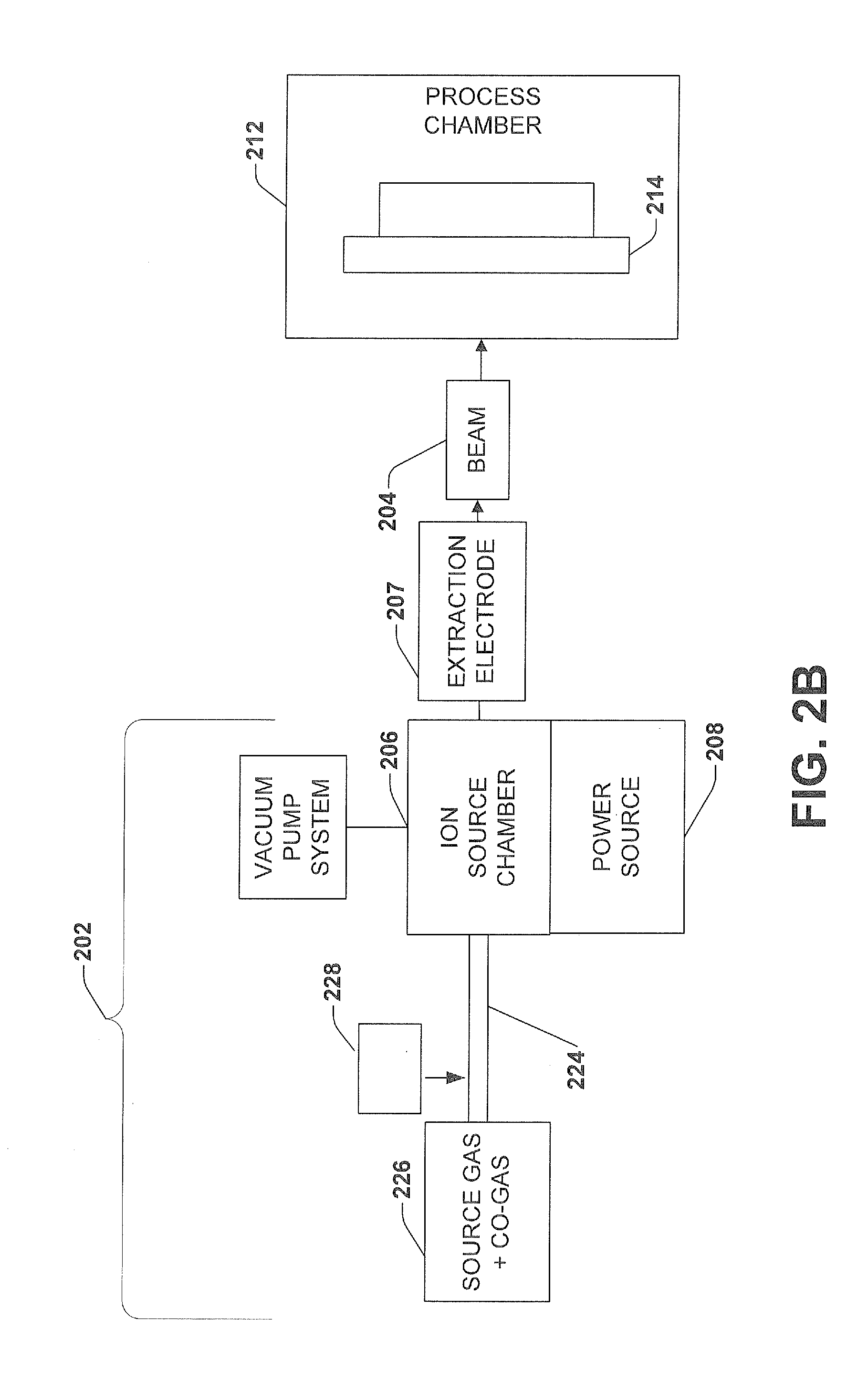
[0020]Referring initially to FIG. 2, an ion implantation system 200 suitable for implementing one or more aspects of the invention is depicted in block diagram form.

[0021]The system 200 includes an ion source assembly 202 for producing an ion beam 204 along a beam path. The ion beam assembly 202 includes, for example, an ion source chamber 206 with an associated power source 208. The ion source chamber 206 may, for example, comprise a relatively long plasma confinement chamber from which an ion beam is extracted and accelerated. An extraction electrode 207 is positioned for extraction of an ion beam from the ion source chamber 206.

[0022]A source gas supply 21...


PUM

PropertyMeasurementUnit
beam currentaaaaaaaaaa
ion source lifetimeaaaaaaaaaa
chemicalaaaaaaaaaa

Abstract

A system, apparatus and method for increasing ion source lifetime in an ion implanter are provided. Oxidation of the ion source and ion source chamber poisoning resulting from a carbon and oxygen-containing source gas is controlled by utilizing a hydrogen co-gas, which reacts with free oxygen atoms to form hydroxide and water.

Description

FIELD OF INVENTION[0001]The present invention relates generally to semiconductor device fabrication and ion implantation, and more particularly to a method of improving performance and extending the lifetime of an ion source in an ion implanter.BACKGROUND OF THE INVENTION[0002]Ion implantation is a physical process that is employed in semiconductor device fabrication to selectively implant dopant into semiconductor and / or wafer material. Thus, the act of implanting does not rely on a chemical interaction between a dopant and semiconductor material. For ion implantation, dopant atoms / molecules are ionized, accelerated, formed into a beam, analyzed, and swept across a wafer, or the wafer is swept through the beam. The dopant ions physically bombard the wafer, enter the surface and come to rest below the surface, at a depth related to their energy.[0003]Referring to FIG. 1, the system 100 includes an ion source 102 for producing an ion beam along a beam path. A beamline assembly 110 is...

Claims


Application Information

Patent Timeline
Patent Type & Authority Applications(United States)
IPC IPC(8): C23C14/48H05H15/00
CPCH01J27/022H01J37/08H01J2237/08H01J2237/006H01J37/3171H01J37/317
Inventor COLVIN, NEIL K.HSIEH, TSEH-JEN
Owner AXCELIS TECHNOLOGIES
Why Eureka
Try Eureka