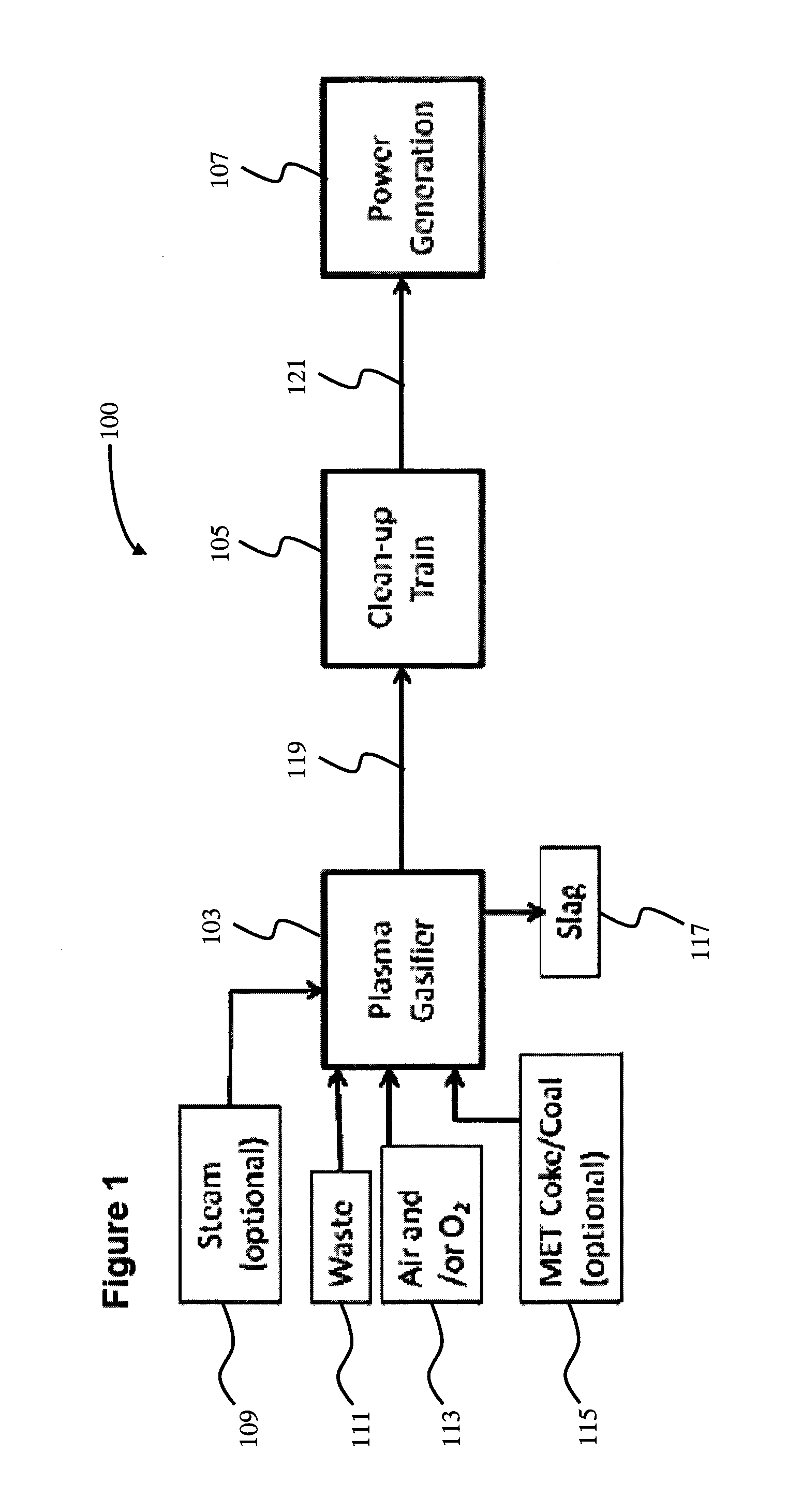
Process and System for Syngas Treatment

a technology of process and system, applied in the direction of combustible gas production, combustible gas purification/modification, energy input, etc., can solve the problems of inability to shut down the cooling system of a 24/7 power generation facility, inability to effectively manage waste, and difficulty in cleaning up this widely varying crude syngas stream

Active Publication Date: 2012-05-24
MILLENNIUM EFW LTD
View PDF8 Cites 19 Cited by
  • Summary
  • Abstract
  • Description
  • Claims
  • Application Information

AI Technical Summary

Benefits of technology

[0012]The instant invention solves problems associated with conventional processes by providing a process and system for treating a crude syngas stream.

Problems solved by technology

The effective management and utilization of waste is a global issue.
One of the challenges of carrying out a waste plasma gasification process is that the widely varying nature of the waste can lead to a widely varying gas and and hydrocarbon compositions as well as particulate amounts and sizes coming out of the gasifier, which shall herein be defined as the “crude syngas stream”.
The clean-up of this widely varying crude syngas stream is particularly challenging if the final product of the overall process is power, especially power that is produced with a gas turbine, reciprocating engine, or an internal combustion engine.
Despite the potential for a wide variation of hydrocarbon compositions and / or tars, the cooling system of a 24 / 7 power generation facility cannot afford to be shut down due to fouling issues caused by the formation of tars at an undesired location in the process.
US Patent Publication No. 2009 / 0133407 A1 discloses a particulate removal system but do not address the high particulate loads that are typical of syngas formed from waste.
The heat recovery system of US Patent Publication No. 2009 / 0133407 A1 is less desirable and less robust for waste gasification as it may be less tolerant to the wide range of metal, particulate and condensable by-products present in the stream exiting the gasifier which may lead to tar formation.
US Patent Publication No. 2008 / 210089 A1 fails to disclose co-scrubbing of HCl and NH3 and does not disclose COS hydrolysis for sulfur removal.
The limitation of this patent's process is that it will not allow for complete sulfur removal, particularly that in the form of COS.
The separate removal of HCl and NH3 in the US Patent Publication No. 2008 / 210089 A1 requires more unit operations to remove HCl and NH3 to desired levels, which requires more equipment, more energy and less efficient processing.

Method used


Image

  • Process and System for Syngas Treatment
  • Process and System for Syngas Treatment
  • Process and System for Syngas Treatment

Examples


example 1

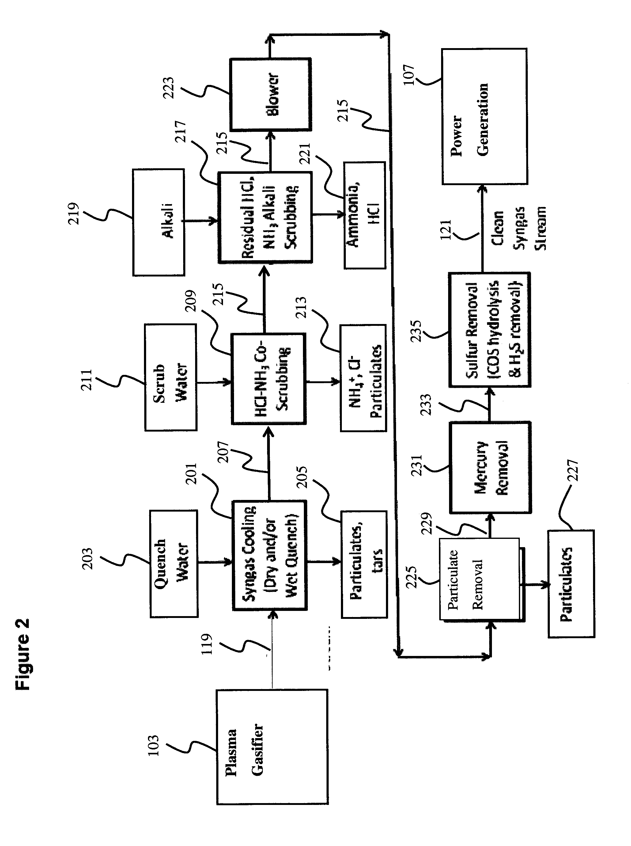
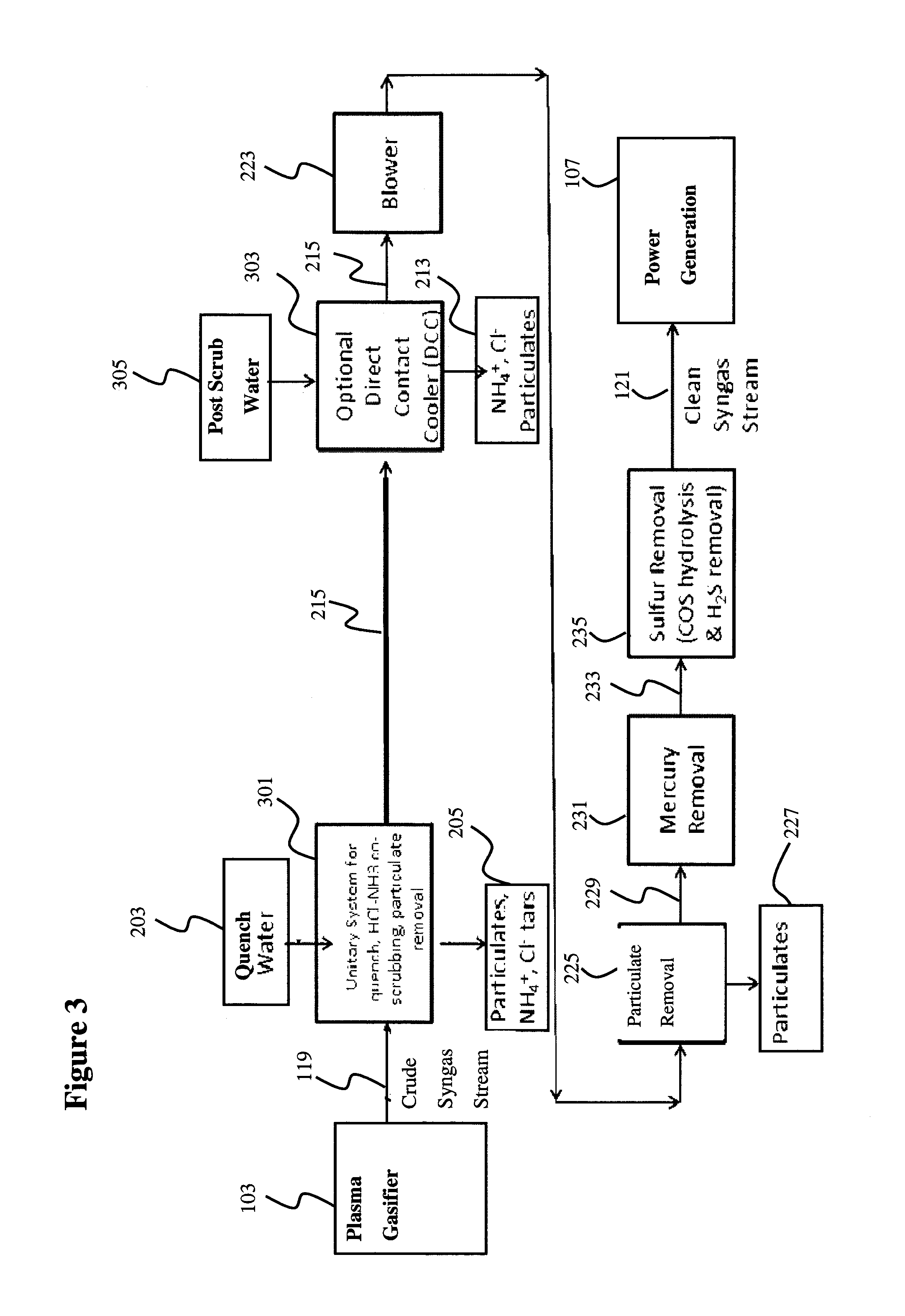
[0062]A crude syngas stream having 40,000 mg / Nm3 of particulates at a temperature of 1800° F. (982° C.) and a pressure of 0 psig is input at 65,000 Nm3 / hr into a syngas clean-up train. The crude syngas stream is fed to a dual Venturi scrubber where the gas is cooled with 290-445 m3 / hr of water, to between 150-200° F. (66-93° C.). Simultaneously a significant portion of the particulates, NH3 and HCl is removed. Tar removal is enhanced by using a large quantity of water at a fast quenching rate in the dual Venturi scrubber.

[0063]Particulate removal in the dual Venturi scrubber could be between 50-90% depending on the particle size distribution. In this example, particulate concentration of the quenched syngas stream is about 10,000 mg / Nm3. The gas passes through a direct contact cooler where the gas is further cooled to about 110° F. (43° C.), particulates are removed and HCl and NH3 are further removed. 90-99% of the input 3000 ppm NH3 and 95-99% of the input 3000 ppm HCl are removed...

example 2

[0064]A crude syngas stream having 40,000 mg / Nm3 of particulates at a temperature of 1800° F. (982° C.) and a pressure of 0 psig is input at 65,000 Nm3 / hr into a syngas clean-up train. The crude syngas is fed to a dual Venturi scrubber where the gas is cooled with 290-445 m3 / hr of water, to between 150-200° F. (66-93° C.). Simultaneously a significant portion of the particulates, NH3 and HCl is removed. Tar removal is enhanced by using a large quantity of water at a fast quenching rate in the Venturi.

[0065]Particulate removal in the dual Venturi could be between 50-90% depending the particle size distribution. In this example, particulate concentration of the quenched syngas stream is about 10,000 mg / Nm3. The gas passes through a direct contact cooler where the gas is further cooled to about 110° F. (43° C.), particulates are removed and HCl and NH3 are further removed. 90% of the input 1000 ppm NH3 and 95-99% of the input 3000 ppm HCl are removed by passing through the dual venturi...

example 3

[0068]A crude syngas stream having 25,000 mg / Nm3 of particulates at a temperature of 1800° F. (982° C.) and a pressure of 0 psig is input at 65,000 Nm3 / hr into a syngas clean-up train. The crude syngas stream is fed to a dual Venturi scrubber where the gas is cooled with 290-445 m3 / hr of water, to between 150-200° F. (66-93° C.). Simultaneously a significant portion of the particulates, NH3 and HCl is removed. Tar removal is enhanced by using a large quantity of water at a fast quenching rate in the dual Venturi scrubber.

[0069]Particulate removal in the dual Venturi scrubber could be between 50-90% depending on the particle size distribution. In this example, particulate concentration of the quenched syngas stream is about 2,000 mg / Nm3. The gas passes through a direct contact cooler where the gas is further cooled to about 110° F. (43° C.), particulates are removed and HCl and NH3 are further removed. 90-99% of the input 3000 ppm NH3 and 95-99% of the input 3000 ppm HCl are removed ...


PUM

PropertyMeasurementUnit
temperatureaaaaaaaaaa

Abstract

A process for the clean-up of a crude syngas stream having widely varying composition and particulate load. The process includes quenching the crude syngas stream with a liquid stream to cool the syngas stream and remove particulates, tars and heavier hydrocarbon compounds. The process further includes co-scrubbing the syngas stream to remove both HCl and NH3 from the syngas stream, removing particulate matter from the syngas stream, and removing sulfur from the syngas stream. A syngas treatment system is also disclosed.

Description

[0001]This Application claims the benefit of U.S. Provisional Application No. 61 / 347496, filed on May 24, 2010. The disclosure of this Application is hereby incorporated by reference.BACKGROUND OF THE INVENTION[0002]The present disclosure is directed to a process and system for the generation and treatment of syngas. In particular, the present disclosure is directed to a process and system for the treatment of a crude syngas stream produced by the plasma gasification of waste, including municipal solid waste (MSW).[0003]The effective management and utilization of waste is a global issue. Current waste management techniques, as suggested by regulatory agencies, such as the U.S.[0004]Environmental Protection Agency (EPA), include source reduction first, recycling and composting second, and, finally, disposal in landfills or waste combustors. Other techniques of managing waste include converting the waste to energy involving processes such as incineration and pyrolysis. There are many ...

Claims


Application Information

Patent Timeline
Patent Type & Authority Applications(United States)
IPC IPC(8): B01D53/00C01B3/52B01D53/14C01B3/50
CPCB01D53/52C10J2300/1238B01D53/64B01D53/68B01D53/75B01D53/8606B01D2251/902B01D2252/103B01D2253/102B01D2253/1124B01D2255/20738B01D2255/20761B01D2255/20792B01D2255/2092B01D2256/16B01D2256/20B01D2257/2045B01D2257/304B01D2257/308B01D2257/406B01D2257/602C10K1/04C10K1/101C10K1/32C10K1/34Y02E20/16Y02E50/12C10J2300/1643C10J3/18C10K1/028C10K1/06C10K1/103C10K1/125C10J2300/0946B01D53/58Y02E50/10Y02P20/129
Inventor KRISHNAMURTHY, GOWRIHIGDON, III, CHARLES ROLANDKRETZ, CHRISTINE PECKGAGLIARDI, CARMINE RICHARDDUFFY, KEVIN M.HSU, KUO-KUANG
Owner MILLENNIUM EFW LTD
Why Eureka
Try Eureka