
Rare earth magnet molding and method for manufacturing the same

a rare earth magnet and molding technology, applied in the field of magnet molding, can solve the problems of affecting the quality of the magnet particles, and the inability to maintain excellent magnetic characteristics, etc., to achieve the effect of reducing the area of the interface at which the chemical reaction is caused, increasing the rate of inner defects that inhibit the magnetic characteristics of the magnet particles, and relatively reducing the influence of degradation on the magnetic characteristics

Inactive Publication Date: 2012-06-21
NISSAN MOTOR CO LTD
View PDF16 Cites 14 Cited by
  • Summary
  • Abstract
  • Description
  • Claims
  • Application Information

AI Technical Summary

Benefits of technology

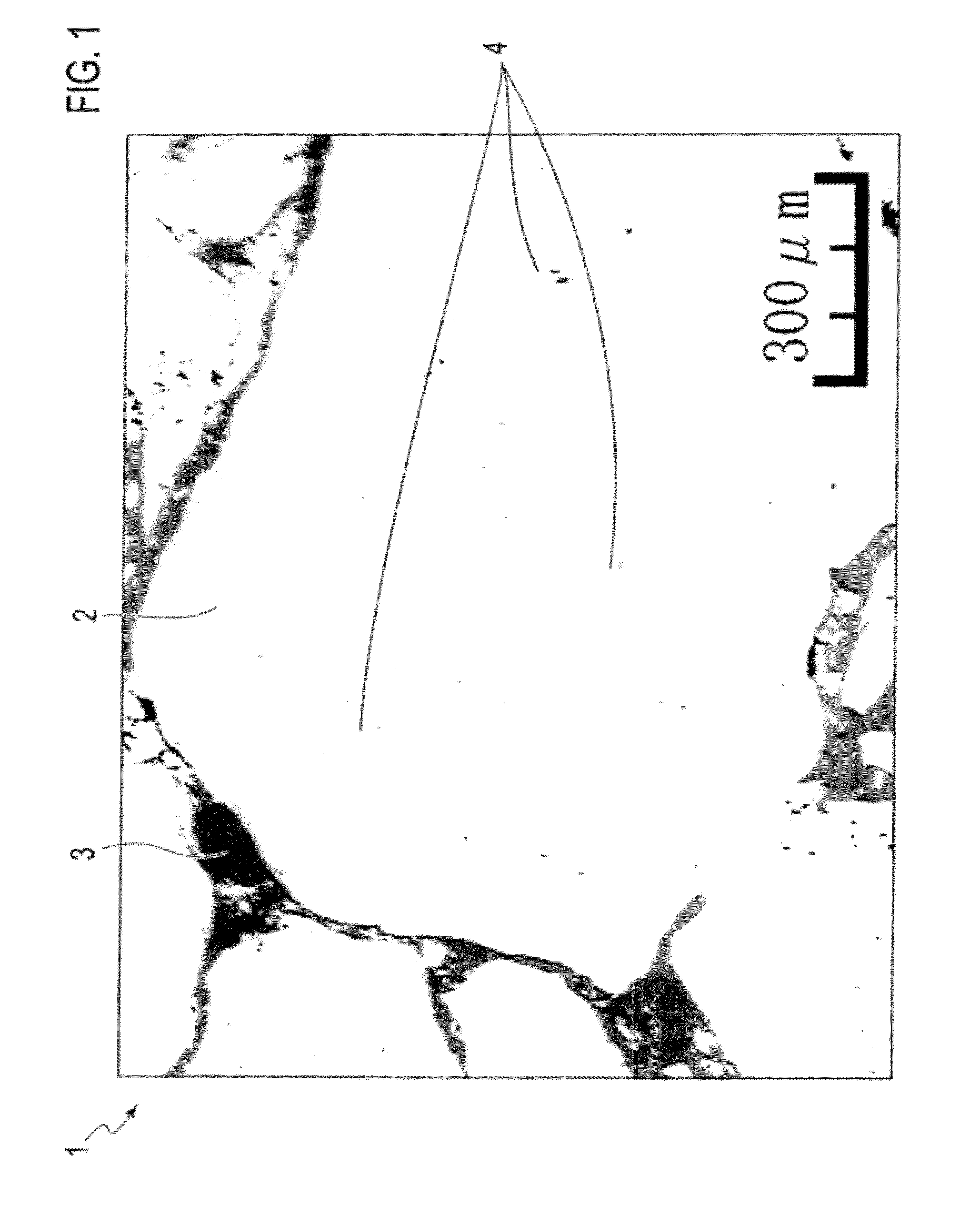
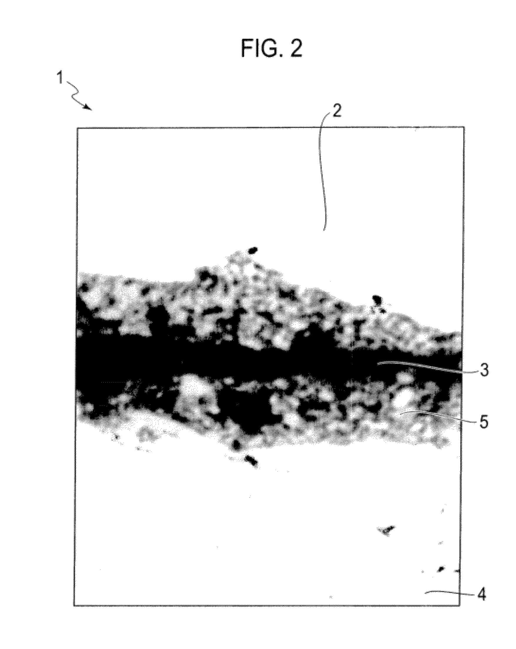
The present invention provides a rare earth magnet molding with excellent resistance to heat in motor environments or the like while maintaining high magnetic characteristics (coercive force). This is achieved by controlling particle diameters of the magnet particles and distributing segregation regions in the rare earth magnet particles. The method includes covering a surface of raw material magnetic powder with a single substance of at least one element selected from the group consisting of Dy, Tb, Pr, and Ho or an alloy thereof to obtain surface-modified raw material magnetic powder, subjecting the obtained surface-modified raw material magnetic powder to pressure molding under a heating atmosphere while subjecting to magnetic orientation in a magnetic field to obtain an anisotropic rare earth magnet, covering surfaces of rare earth magnet particles obtained by pulverizing the obtained anisotropic rare earth magnet with an insulating phase to obtain a magnet molding precursor, and heating the obtained magnet molding precursor under pressure.

Problems solved by technology

On the other hand, if the particle diameters of the magnet particles are excessively increased, a rate of inner defects that inhibit the magnetic characteristics of the magnet particles is increased, or variations in direction of crystal particles become large.
As a result, even if the method described in Patent Literature 1 is used, the effect of the improved magnetic characteristics (coercive force) does not necessarily reach deep into the magnet particles, and the excellent magnetic characteristics may not be maintained.

Method used


Image

  • Rare earth magnet molding and method for manufacturing the same
  • Rare earth magnet molding and method for manufacturing the same
  • Rare earth magnet molding and method for manufacturing the same

Examples


example 1

[0111]Powder of a Nd—Fe—B type anisotropic magnet prepared by means of an HDDR method was used as raw material magnetic powder. Specific procedures for preparation are as follows.

[0112]First, an ingot having a composition defined as “Nd: 12.6%, Co: 17.4%, B: 6.5%, Ga: 0.3%, Al: 0.5%, Zr: 0.1%, and Fe: balance (% by mass)” was prepared. The ingot was retained at 1120° C. for 20 hours for homogenization. The homogenized ingot was then heated from a room temperature up to 500° C. and retained at the same temperature in a hydrogen atmosphere, and then further heated up to 850° C. and retained at the same temperature.

[0113]Subsequently, the ingot was retained at 850° C. in vacuum, and then cooled down to obtain an alloy including a fine ferromagnetic phase recrystallization texture. The alloy was powdered under an argon atmosphere by means of a jaw crusher and a braun mill and thereby formed into rare earth magnet raw material magnetic powder having an average particle diameter of 300 μm...

example 2

[0129]A rare earth magnet molding was obtained in the same manner as Example 1 except that praseodymium tri-isopropoxide was used instead of dysprosium tri-isopropoxide as rare earth alkoxide to form an insulating phase containing Pr oxide. The concentration of Pr in the praseodymium surface treating solution was analyzed by means of ICP. The coating amount of the solution was adjusted in such a manner that the amount was 40 mg in total with respect to 10 g of the magnet particles.

example 3

[0130]A rare earth magnet molding was obtained in the same manner as Example 1 except that raw material magnetic powder for a sintered magnet was used instead of the raw material magnetic powder prepared by means of the HDDR method. The raw material magnetic powder was prepared as follows.

[0131]An alloy mixed to have a composition defined as Nd: 31.8, B: 0.97, Co: 0.92, Cu: 0.1, Al: 0.24, and balance: Fe (% by mass) was processed into an alloy ribbon having a thickness of 0.2 mm to 0.3 mm by means of a strip cast method. Subsequently, a container was filled with the alloy ribbon and placed in a hydrogen treating device. The hydrogen treating device was filled with a hydrogen gas atmosphere with pressure of 500 kPa so that hydrogen was adsorbed to the alloy ribbon at room temperature. Then, the atmosphere was converted into argon gas, and the pressure was decreased to 10−5 Pa to release hydrogen. Through such hydrogen treatment, the alloy ribbon was processed into amorphous powder ha...


PUM

PropertyMeasurementUnit
particle diameteraaaaaaaaaa

Abstract

A rare earth magnet molding (1) of the present invention includes rare earth magnet particles (2), and an insulating phase (3) present among the rare earth magnet particles. Segregation regions (4) in which at least one element selected from the group consisting of Dy, Tb, Pr and Ho is segregated are distributed in the rare earth magnet particles (2). Accordingly, the rare earth magnet molding that has excellent resistance to heat in motor environments or the like while maintaining high magnetic characteristics (coercive force) is provided.

Description

TECHNICAL FIELD[0001]The present invention relates to a magnet molding and a method for manufacturing the same. The magnet molding provided by the present invention is used in, for example, a motor.BACKGROUND ART[0002]With regard to a conventional magnet molding used for a motor or the like, a ferrite magnet that is a permanent magnet has been mainly used. However, in association with an increase in performance and decrease in size of a motor, usage of a rare earth magnet having more excellent magnetic characteristics has increased in recent years.[0003]A rare earth magnet such as a Nd—Fe—B type magnet used for a motor or the like has a problem with low resistance to heat. In response to this problem, a method for covering magnet particles in a magnet with an insulating substance to three-dimensionally isolate flow paths of eddy current and decrease the amount of heat generation has been proposed. In addition, various technologies according to the type and production method of the i...

Claims


Application Information

Patent Timeline
Patent Type & Authority Applications(United States)
IPC IPC(8): H02K21/00B22F1/00B22F3/12H01F7/02B22F1/08B22F1/16
CPCB22F1/02B22F3/14C22C19/07C22C28/00H01F41/0293H01F1/0572H01F1/0576H01F1/0577H01F41/0266C22C38/005H01F1/0573B22F1/16B22F1/08
Inventor KAWASHITA, YOSHIOURAMOTO, KIYOHIROMIYAMOTO, TAKASHIYASUDA, YOSHITERU
Owner NISSAN MOTOR CO LTD
Learn More