
Blast Resistant, Non-Magnetic, Stainless Steel Armor

Inactive Publication Date: 2012-06-21
CRS HLDG INC
View PDF2 Cites 7 Cited by
  • Summary
  • Abstract
  • Description
  • Claims
  • Application Information

AI Technical Summary

Benefits of technology

[0009]The foregoing tabulations are provided as convenient summaries and are not intended thereby to restrict the lower and upper values of the ranges of the individual elements of the alloy used in this invention for use solely in combination with each other or to restrict the various broad and preferred ranges of the elements for use solely in combination with each other. Thus, one or more of the

Problems solved by technology

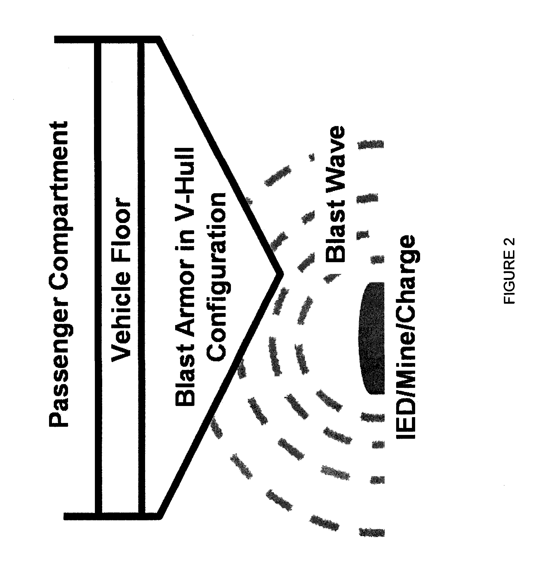
The use of improvised explosive devices (IED's) and land mines by military insurgents causes significant destruction of military equipment and substantial injury and loss of life of military personnel.
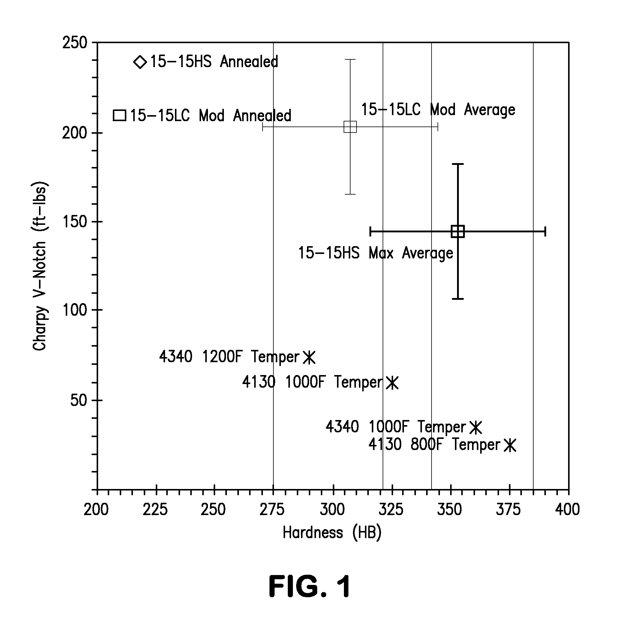
Martensitic steels provide high strength, but less than desirable energy absorption compared to aluminum alloys.
On the other hand, aluminum alloys provide good energy absorption, but lower strength than martensitic steels.

Method used


Image

  • Blast Resistant, Non-Magnetic, Stainless Steel Armor
  • Blast Resistant, Non-Magnetic, Stainless Steel Armor
  • Blast Resistant, Non-Magnetic, Stainless Steel Armor

Examples


working examples

[0021]In order to demonstrate the process and product of the present invention, two heats were melted and processed into plate. The plate material was then tested to determine the relevant mechanical properties, ballistic tolerance, and blast resistance of the as-processed material. The weight percent compositions of the two heats are set forth in Table 1 below.

TABLE 1ElementHeat 1Heat 2C0.0350.027Mn17.9918.41Si0.360.37P0.0220.028S0.001Cr17.6618.56Ni0.941.97Mo0.770.74Cu0.060.06N0.520.57B0.00190.0024

The balance of each heat is iron and usual impurities. Heat 1 was ARC-AOD melted whereas Heat 2 was ARC-ESR melted.

example 1

[0022]The objective of this example was to produce plate material in accordance with the first process described above. Material from the ingot of Heat 1 and from the ingot of Heat 2 was hot worked to provide slabs 2.58 inches (6.55 cm) thick. The slab formed from Heat 1 was heated to a temperature of 1650° F. (899° C.) and hot rolled to 0.55 inch (13.97 mm) thick plate. The slab formed from Heat 2 was heated to a temperature of 1650° F. (899° C.) and hot rolled to 0.53 inch (13.5 mm) thick plate. For both heats, the plate material was quenched with water within about 10 minutes of the last rolling pass. Longitudinal and transverse samples for hardness, tensile, and toughness testing were cut from the plates and machined to form standard size test specimens. The results of room temperature hardness, tensile, and Charpy V-notch toughness testing are shown in Tables 2A and 2B below including the Brinell hardness number (BHN), the 0.2% offset yield strength (YS) and ultimate tensile st...

example 2

[0023]The objective of this example was to produce plate material using the two-step process described above. Additional material from the ingot of Heat 2 was hot worked to provide slabs nominally 5 inches (12.7 cm) thick. The slabs were then hot rolled to intermediate thicknesses. A first slab was hot rolled from a start temperature of about 2100° F. (1149° C.) to an intermediate thickness of about 0.72 inches (18.3 mm). A second slab was rolled from a start temperature of about 2100° F. (1149° C.) to an intermediate thickness of about 0.905 inches (23 mm). A third slab was rolled from a start temperature of about 2100° F. (1149° C.) to an intermediate thickness of about 1.25 inches (31.75 mm). A fourth slab was rolled from a start temperature of about 2100° F. (1149° C.) to an intermediate thickness of about 2.55 inches (6.48 cm). The intermediate forms were rapidly cooled with water within about 5 minutes of completion of the last rolling pass on each intermediate slab. After the...


PUM

PropertyMeasurementUnit
Temperatureaaaaaaaaaa

Abstract

An article of manufacture formed of an alloy having the following weight percent composition is described.Carbon0.25 max.Manganese 14-20 Siliconup to 2.0Phosphorus0.05 max.Sulfur 0.5 max.Chromium 12-22 Nickel 3.5 max.Molybdenum0.5-4  Copper 2.0 max.Nitrogen0.2-0.8Boron0.06 max.The balance of the alloy is iron and the usual, inevitable impurities found in commercial grades of stainless steel alloys. Optionally, the alloy may contain niobium, titanium, vanadium, zirconium, hafnium, and tungsten in a combined amount of up to about 0.5%. An intermediate form of the article is armor plate made from the alloy. In accordance with another aspect of the present invention, the plate is shaped to form an armor part that is attached to a larger structure to provide resistance to an explosion fragments or a ballistic projectile.

Description

BACKGROUND OF THE INVENTION[0001]1. Field of the Invention[0002]This invention relates to blast resistant articles of manufacture and in particular to such an armor article made from a corrosion resistant, non-magnetic, high strength, high toughness steel alloy and to a process for making the armor article.[0003]2. Description of the Related Art[0004]The use of improvised explosive devices (IED's) and land mines by military insurgents causes significant destruction of military equipment and substantial injury and loss of life of military personnel. Because of such threats, a need has arisen among armored vehicle manufacturers for new blast-resistant materials which provide a better combination of strength with energy absorption capability than the materials currently in use. Energy absorption capability is related to the toughness of a material. The toughness of a material has been defined as the ability to absorb energy and deform plastically before fracturing. Two known families o...

Claims


Application Information

Patent Timeline
IPC IPC(8): C22C38/58B22D25/06C21D8/02C22C30/00
CPCC21D6/002C21D6/005C21D8/0205C21D8/0226C21D8/0231C21D8/0273C22C38/54C22C38/58F41H5/045C22C38/001C22C38/02C22C38/42C22C38/44C21D9/42
Inventor THOMPSON, PETER T.PILLIOD, CHRISTOPHER F.
Owner CRS HLDG INC
Learn More