Multi-stage adsorption system for gas mixture sparation

a technology of adsorption system and gas mixture, which is applied in the direction of dispersed particle separation, separation process, waste based fuel, etc., can solve the problems of difficult to adapt that type of technology to produce lng economically on a small scale, different lng standards from pipeline standards, and significant differences in separation requirements, etc., to achieve the effect of less power and smaller vessels

Active Publication Date: 2012-07-19
KENT S KNAEBAL & ASSOC
View PDF9 Cites 9 Cited by
  • Summary
  • Abstract
  • Description
  • Claims
  • Application Information

AI Technical Summary

Benefits of technology

[0030]Accordingly, one aspect of the present process is to provide a separation system that treats a feed gas comprised of, at a minimum, methane, carbon dioxide, nitrogen, oxygen, and water vapor, and produces enriched methane suitable for liquefaction or pipeline distribution, but that avoids the problems associated with conventional systems. Another aspect of the present process is to treat at least 10 scfm but less than 20,000 scfm of feed gas. Another aspect of the present process is to enable production to be safer and more cost effective than conventional systems, by using a sequence of cyclic adsorption stages in one system. Another aspect of the present process is to provide for the control of the delivery and quality of gas from each stage of the system, such that the final quality of the product gas is acceptable for liquefaction or pipeline distribution.
[0033]In the third stage of either the first or second embodiments, or the second stage of the third embodiment, it is possible to vary the nitrogen and oxygen content of the methane-rich product by changing the operating conditions or the adsorbent. For example, it is possible to obtain a methane-rich product having an oxygen content of approximately 0.1% to 1%, from a feed that originally exhibited an oxygen-to-methane ratio of about 4%. The higher value requires less power and somewhat smaller vessels. The purified methane stream is produced at ambient pressure, though it may be compressed to an arbitrary pressure.

Problems solved by technology

LNG standards, however, are different from pipeline standards, and the separation requirements are significantly different.
For several reasons, it is difficult to adapt that type of technology to produce LNG economically on a small scale, such as is pertinent here.
Although these methods are useful for liquefaction, none is capable of purifying the methane-bearing feed gas on a continuous basis, however, so they will not be described in any detail.
The spread of boiling points implies that, if much oxygen is present, a hazardous situation may arise since oxygen and methane may tend to be concentrated together, which would be a hazardous mixture.
In addition, carbon dioxide and water vapor pose potential processing problems because they can solidify at the temperature at which methane liquefies, if their partial pressures are too high.
Because CD involves contacting the liquid and vapor phases of the mixture to be separated, formation of the solid phases of carbon dioxide and / or water can physically disrupt the separation, i.e., block the flow of liquid and vapor in a distillation column.
In addition, solidification may cause a problem in the cold-box heat exchanger, which partially cools the feed mixture to cryogenic conditions, or in the Joule-Thomson valve, which also contributes to cooling.
It, however, is complex, which leads to high capital cost and is impractical to apply to smaller feed streams.
The primary limitations of these processes are their complexity and the associated capital costs.
These are not particularly economical means for removing carbon dioxide.
Since methane is the major component in the mixture, this process is energy-intensive and expensive to operate.
In addition, the equipment for this process tends to be expensive, on account of the refrigeration unit and ancillary heat exchangers.
Likewise, the dryer does not remove methane to an appreciable extent.
In addition to the disadvantage of complexity, the absorbents tend to decompose and to lose effectiveness, produce foam, or become viscous as time proceeds, due to adverse chemical reactions and due to absorption of dilute contaminants.
Absorbents, which cannot be fully regenerated, continue to accumulate contaminants, eventually releasing some of the contaminants into the methane-rich product.
Consequently, absorbents have the disadvantage of routinely requiring replenishment.
In order to recover sufficiently pure methane, e.g., to meet LNG standards, on account of the number of absorption and regeneration units, the energy intensity, and the absorbent replenishment cost, the capital and operating expenses are very high.
Such processes use membrane modules combined as stages to perform the separation, and they exhibit a tradeoff between the recovery and purity of the methane-rich product that is recovered, such that it is impossible with current membrane materials to attain both high purity and high recovery on a single-pass basis.
Consequently, to attain high recovery at reasonable purity requires substantial recycle, and power input.
Membrane processes are expensive for applications such as this, having high purity constraints, on account of high equipment and power costs (largely due to recycle which is necessary to meet purity requirements), which are not feasible except for very low feed flow rates
These hybrid systems are complex and expensive, which limit their use.
This system is complex and the related capital costs limit its usefulness.
“Cold Methanol” separations, as they are called, are effective, but they do not scale well to smaller LFG sources because of the system complexity, capital costs, and operating costs associated with the combined absorption and distillation processing equipment.

Method used


Image

  • Multi-stage adsorption system for gas mixture sparation
  • Multi-stage adsorption system for gas mixture sparation
  • Multi-stage adsorption system for gas mixture sparation

Examples


examples

[0064]Unless explicitly stated otherwise, compositions that follow are listed in volumetric percentages, and the abbreviated unit ppm refers to parts-per-million by volume. Pressures are given in pounds per square inch, absolute, abbreviated as psia. Flow rates are listed as standard cubic feet per minute, abbreviated scfm, in this case 1 pound mole is equivalent to 379.4 standard cubic feet (scf).

first embodiment

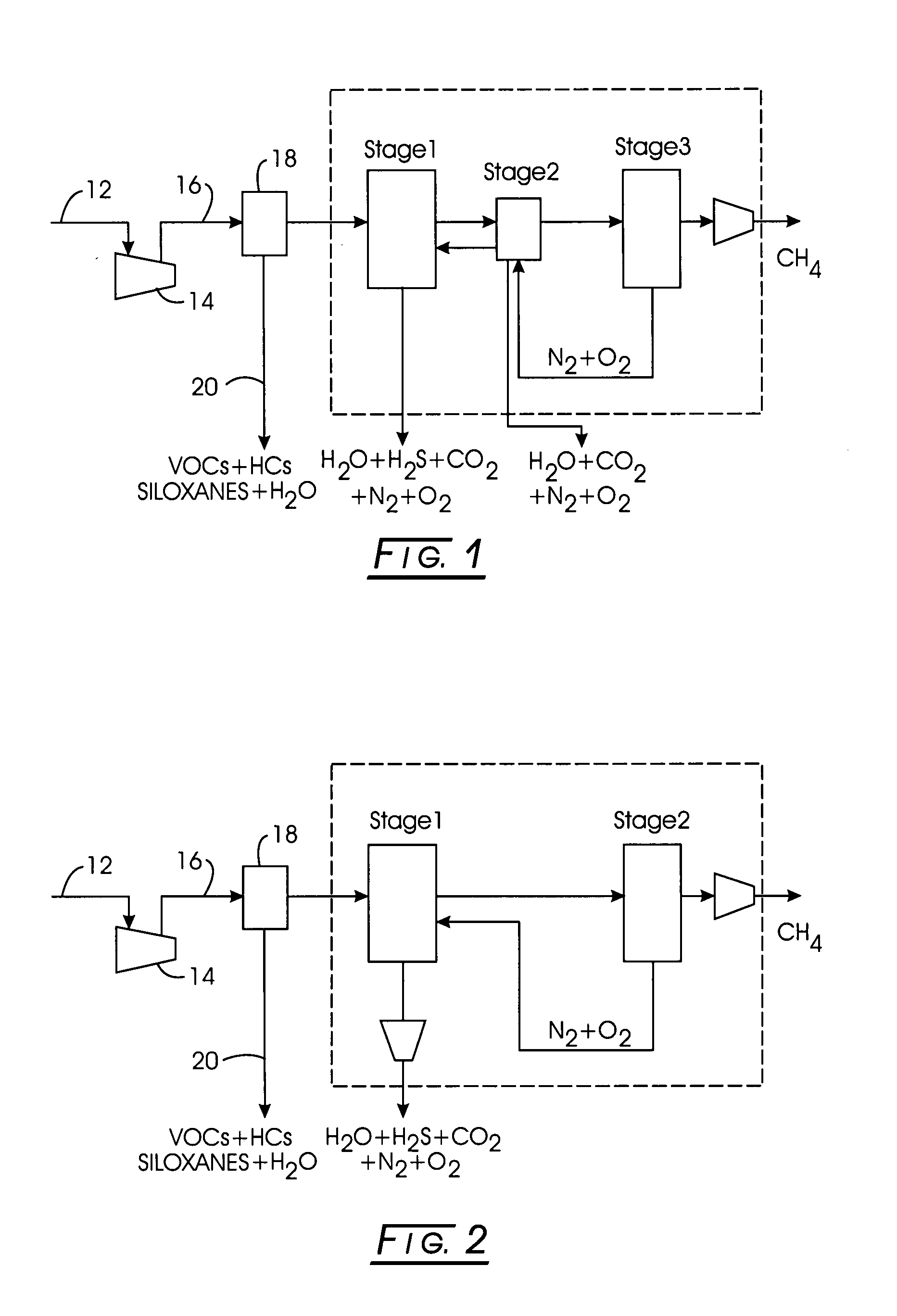
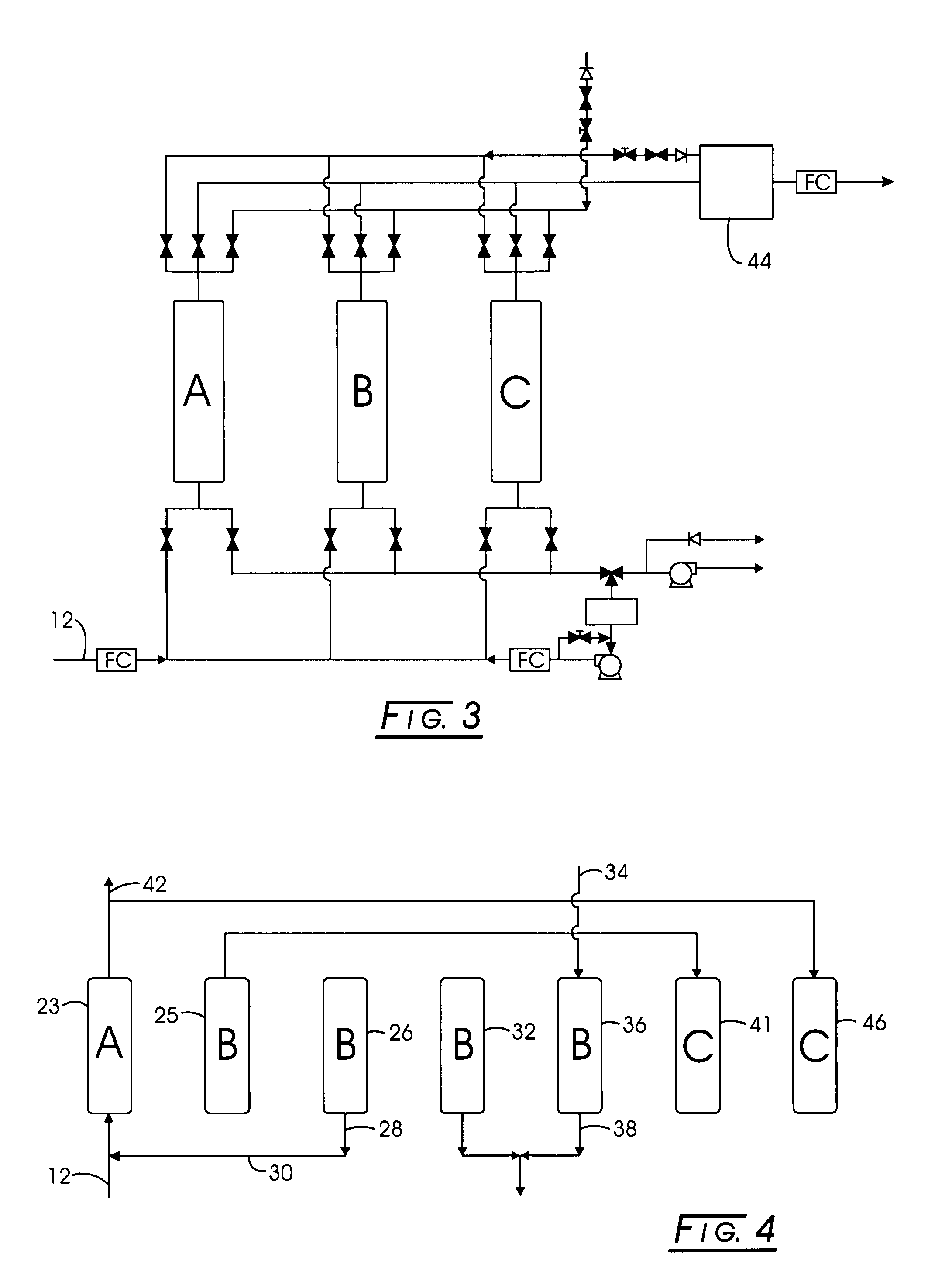
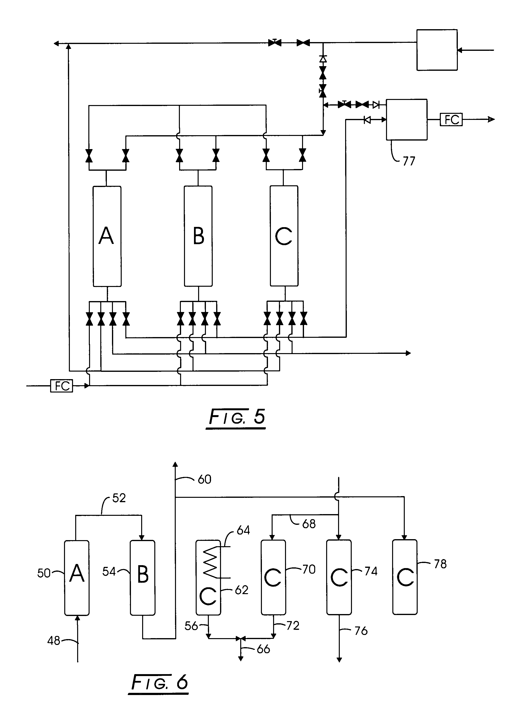
[0065]Stage 1: Methane-bearing feed containing about: 52% methane, 34% carbon dioxide, 12% nitrogen, 2% oxygen, and 0.1% water vapor was separated using silica gel as the adsorbent in Stage 1. The maximum pressure, PH, was about 70 psia, the minimum pressure, PL, was about 0.8 psia, and the intermediate pressure, PA, was about 16 psia, while the intermediate pressure, PM, was about 35 psia. The effluent composition of the purified product was about 74% methane, 0.3% carbon dioxide, 23% nitrogen, 3% oxygen, and 0% water vapor. The corresponding time for each of the step is subject to optimization, and depends on the adsorbent, operating conditions, and vessel dimensions. Examples for this case are: 330 seconds for feed, 30 seconds for pressure equalization, 30 seconds for countercurrent blowdown, 160 seconds for evacuation, and 110 seconds for purge, 30 seconds for pressure equalization, and 300 seconds for pressurization. The net feed flow rate, per unit mass of adsorbent, was 0.059...


PUM

PropertyMeasurementUnit
boiling pointsaaaaaaaaaa
dew point temperatureaaaaaaaaaa
sizeaaaaaaaaaa

Abstract

Methane product gas is produced from landfill gas and gob gas either by a three-stage process of PSA-TSA-PSA or PSA-PSA-PSA, or a two-stage process of PSA-PSA.

Description

CROSS-REFERENCE TO RELATED APPLICATIONS[0001]NoneSTATEMENT REGARDING FEDERALLY SPONSORED RESEARCH[0002]Not applicable.BACKGROUND[0003]1. Field of the Process[0004]The present development relates to a method and an apparatus for separating a desired gas component from a gas mixture containing a plurality of gas components. More particularly, the present development relates to a multi-stage adsorption system to separate a methane-bearing feed gas, containing a plurality of components, including, for example, methane, carbon dioxide, nitrogen, oxygen, and water vapor. Other constituents may be present in small quantities in the methane-bearing feed gas, such as, for example, ethane, ethylene, hydrogen, hydrogen sulfide, and propane, with no significant impact on the operation of the present process. The present process produces a methane-rich product gas that meets certain purity requirements, e.g., for liquefaction or for distribution via pipeline, and a byproduct gas containing most ...

Claims


Application Information

Patent Timeline
Patent Type & Authority Applications(United States)
IPC IPC(8): C07C7/12
CPCB01D53/0462B01D53/047B01D53/75B01D2253/102B01D2253/104B01D2253/106B01D2258/05B01D2256/245B01D2257/102B01D2257/104B01D2257/504B01D2257/80Y02E50/346B01D2253/108Y02E50/30
Inventor KNAEBEL, KENT S.
Owner KENT S KNAEBAL & ASSOC
Why Eureka
Try Eureka