Light-reflective anisotropic conductive adhesive and light-emitting device

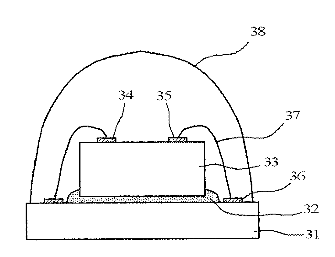
a technology of anisotropic conductive adhesives and light-emitting devices, which is applied in the direction of non-metal conductors, conductors, non-macromolecular adhesive additives, etc., can solve the problems of deteriorating light-emitting efficiency of led elements b>33/b>, and achieve the effects of improving light-emitting efficiency, small dependence of reflecting properties on visible light wavelength, and improving light-emitting efficiency

Active Publication Date: 2012-08-02
DEXERIALS CORP
View PDF39 Cites 37 Cited by
  • Summary
  • Abstract
  • Description
  • Claims
  • Application Information

AI Technical Summary

Benefits of technology

[0012]The light-reflective anisotropic conductive adhesive of the present invention used for anisotropic conductive connection of a light-emitting element to a wiring board includes light-reflective insulating particles. Therefore, this light-reflective anisotropic conductive adhesive can reflect light. In particular, when the light-reflective insulating particle is at least one of inorganic particles selected from the group consisting of titanium oxide particles, boron nitride particles, zinc oxide particles, and aluminum oxide particles, or a resin-coated metal particle formed by coating the surface of scale-like or spherical particles with an insulating resin, since the particles themselves are almost white, the dependence of the reflecting property to the wavelength of the visible light is small. Consequent

Problems solved by technology

However, for the light-emitting device illustrated in FIG. 4, there is the problem that, among the light emitted by the LED element 33, the light having a wavelength of 400 to 500 nm that is output to the uppe

Method used


Image

  • Light-reflective anisotropic conductive adhesive and light-emitting device
  • Light-reflective anisotropic conductive adhesive and light-emitting device
  • Light-reflective anisotropic conductive adhesive and light-emitting device

Examples


example 1

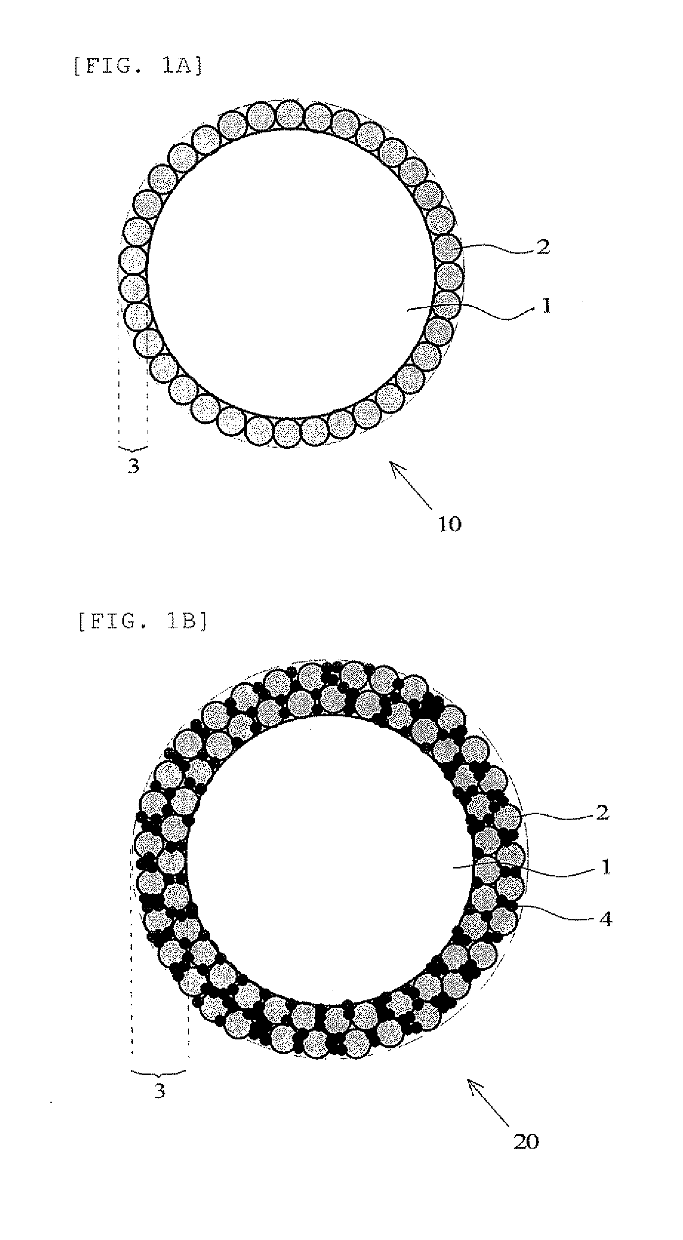
[0061]A light-reflective anisotropic conductive adhesive having a white appearance was obtained by uniformly mixing 12% by volume of a titanium dioxide powder having an average particle size of 0.5 μm (KR-380, Titan Kogyo, Ltd.) as light-reflective insulating particles and 10% by mass of Au-coated resin conductive particles having an average particle size of 5 μm (particles formed by coating a 0.2 μm-thick electroless gold plating on spherical acrylic resin particles having an average particle size of 4.6 μm (Bright 20GNB4.6EH, Nippon Chemical Industrial Co., Ltd.)) as conductive particles in a colorless, transparent thermosetting epoxy binder composition having a refractive index of approximately 1.50 (YX-8000, JER Co. Ltd.: containing 50% by mass of MeHHPA).

(Optical Reflectance Evaluation Test)

[0062]The obtained light-reflective anisotropic conductive adhesive was coated on a white ceramic plate to a dry thickness of 100 μm, and heated for 1 minute at 200° C. to cure. The reflecta...

example 2

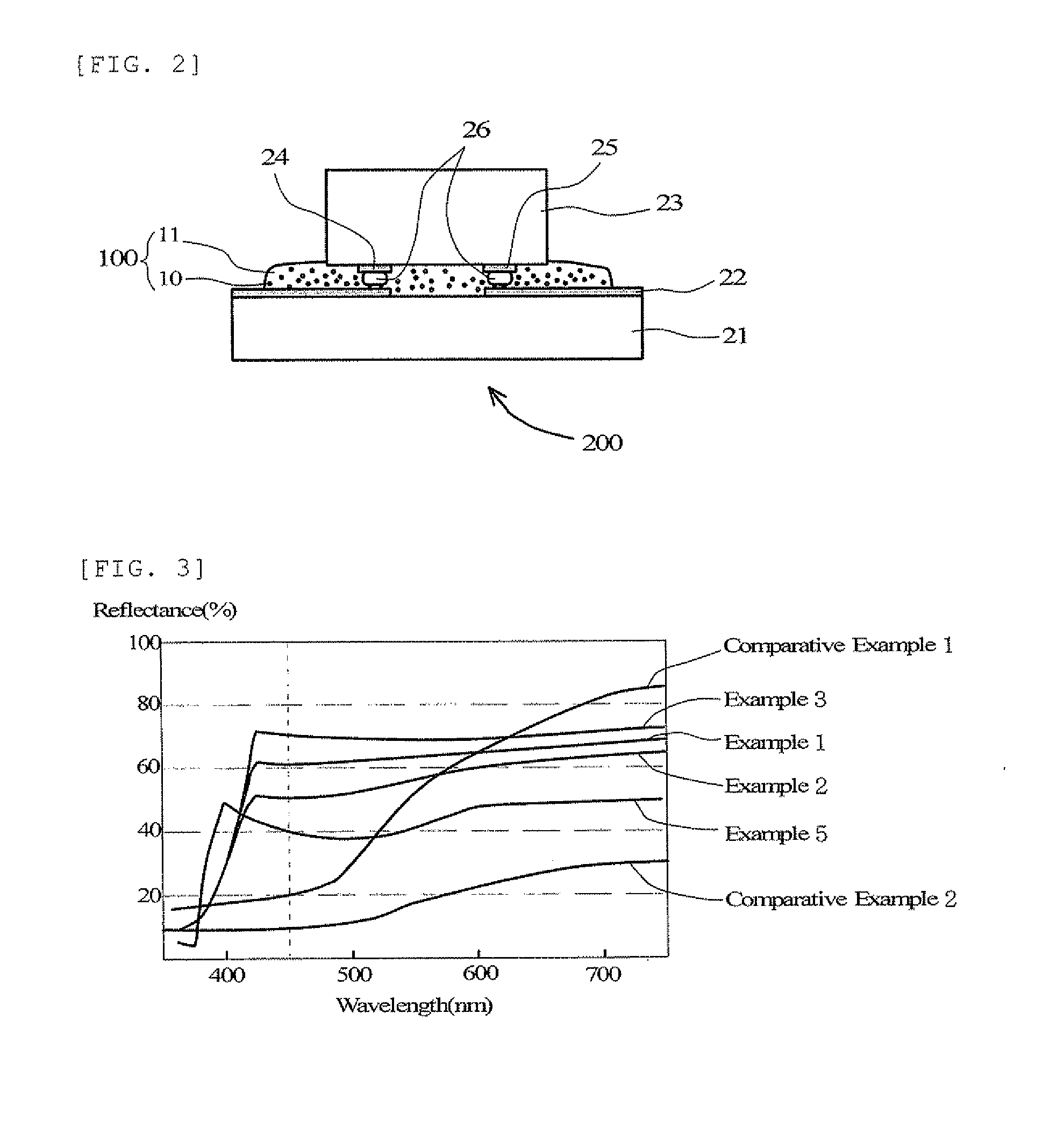
[0065]A light-reflective anisotropic conductive adhesive having a white appearance was obtained in the same manner as in Example 1, except that the blended amount of the titanium dioxide powder was 7% by volume. Further, an optical reflectance evaluation test and a total luminous flux evaluation test for an LED-mounted sample were carried out in the same manner as in Example 1. The obtained results are shown in Table 1. The optical reflectance results are also illustrated in FIG. 3.

example 3

[0066]A light-reflective anisotropic conductive adhesive having a white appearance was obtained in the same manner as in Example 1, except that the blended amount of the titanium dioxide powder was 21% by volume. Further, an optical reflectance evaluation test and a total luminous flux evaluation test for an LED-mounted sample were carried out in the same manner as in Example 1. The obtained results are shown in Table 1. The optical reflectance results are also illustrated in FIG. 3.


PUM

PropertyMeasurementUnit
Percent by massaaaaaaaaaa
Percent by volumeaaaaaaaaaa

Abstract

A light-reflective anisotropic conductive adhesive used for anisotropic conductive connection of a light-emitting element to a wiring board includes a thermosetting resin composition, conductive particles, and light-reflective insulating particles. The light-reflective insulating particles are at least one of inorganic particles selected from the group consisting of titanium oxide, boron nitride, zinc oxide, and aluminum oxide, or resin-coated metal particles formed by coating the surface of scale-like or spherical metal particles with an insulating resin.

Description

TECHNICAL FIELD[0001]The present invention relates to a light-reflective anisotropic conductive adhesive used for anisotropic conductive connection of a light-emitting element to a wiring board, and a light-emitting device formed by using this adhesive to mount a light-emitting element to a wiring board.BACKGROUND ART[0002]Light-emitting devices that use a light-emitting diode (LED) element are widely used. Older-type light-emitting devices are configured by, as illustrated in FIG. 4, joining an LED element 33 to a substrate 31 with a die bond adhesive 32, wire-bonding a p electrode 34 and an n electrode 35 on an upper face of the LED element 33 to a connection terminal 36 on the substrate 31 with a gold wire 37, and then sealing the whole of the LED element 33 with a transparent mold resin 38. However, for the light-emitting device illustrated in FIG. 4, there is the problem that, among the light emitted by the LED element 33, the light having a wavelength of 400 to 500 nm that is ...

Claims


Application Information

Patent Timeline
IPC IPC(8): H01L33/48H01B1/22H01B1/20
CPCC08K3/22C08K3/38C09J9/02C09J11/04H01L33/56H01L33/60C08G18/8175C08G59/42C09J163/00H01L2224/16225H01L2224/32225H01L2224/48091H01L2224/48227H01L2224/73204H01L2224/73265H01L2224/45144H01L2924/07811H01L2224/45147H01B1/22H01L2924/00014H01L2924/00H10K50/00
Inventor NAMIKI, HIDETSUGUKANISAWA, SHIYUKIUMAKOSHI, HIDEAKI
Owner DEXERIALS CORP
Why Eureka
Try Eureka