Eureka AIR delivers breakthrough ideas for toughest innovation challenges, trusted by R&D personnel around the world.

Resist pattern forming process

Active Publication Date: 2012-08-02
SHIN ETSU CHEM IND CO LTD
View PDF2 Cites 5 Cited by
  • Summary
  • Abstract
  • Description
  • Claims
  • Application Information

AI Technical Summary

Benefits of technology

[0029]The resist pattern forming process is characterized in that a softening accelerator having a molecular weight of up to 800 is present in a resist pattern obtained after development. By heating in a practically appropriate temperature range, the resist pattern as developed is subjected to thermal deformation to such an extent that the line width of the pattern may not undergo a change of at least 10%, whereby the resist pattern profile is corrected for minor asperities in a consistent manner. The process is successful in readily forming a resist pattern requiring a more strictly configured profile such as an OPC pattern.

Problems solved by technology

In particular, a problem that the profile of a resist pattern as developed is roughened at the edge is known as “line edge roughness” (LER), with the continuing demand for improvement in this problem.
This approach alone is difficult to accommodate an attempt to form a fine pattern having a line width of less than 65 nm.

Method used


Image

  • Resist pattern forming process
  • Resist pattern forming process
  • Resist pattern forming process

Examples


reference example 1

Synthesis of 1-ethylcyclopentyloxycarbonylmethyl dehydrocholate (A-1)

[0178]

[0179]A mixture of 4.0 g of dehydrocholic acid (S-1), 2.9 g of 1-ethylcyclopentyl chloroacetate (S-2), 1.2 g of triethylamine, 0.2 g of sodium iodide, and 24 g of dimethylformamide was stirred at 80° C. for 48 hours. The reaction mixture was diluted with methylene chloride, subjected to an ordinary aqueous workup, and purified by column chromatography, yielding 4.3 g of 1-ethylcyclopentyloxycarbonylmethyl dehydrocholate (A-1).

reference example 2

Synthesis of 1-ethylcyclopentyl dehydrocholate (A-2)

[0180]

[0181]A mixture of 4.2 g of dehydrocholic acid chloride (S-3), 1.7 g of 1-ethylcyclopentanol (S-4), 0.1 g of 4-dimethylaminopyridine, and 16 g of pyridine was stirred at 60° C. for 16 hours. The reaction mixture was diluted with methylene chloride, subjected to an ordinary aqueous workup, and purified by column chromatography, yielding 3.5 g of 1-ethylcyclopentyl dehydrocholate (A-2).

reference example 3

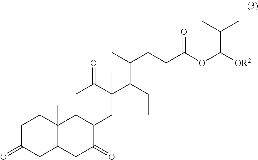
Synthesis of 1-methoxy-2-methylpropyl dehydrocholate (A-3)

[0182]

[0183]At room temperature, 6.1 g of 1-chloro-2-methylpropyl methyl ether (S-5) was added dropwise to a mixture of 20.0 g of dehydrocholic acid (S-1), 6.0 g of triethylamine, and 100 g of tetrahydrofuran, followed by stirring for 1 hour. The reaction mixture was diluted with toluene. After an ordinary aqueous workup, the solvent was distilled off in vacuum. The resulting solid was washed with isopropyl ether and dried in vacuum, yielding 21.9 g of 1-methoxy-2-methylpropyl dehydrocholate (A-3).

[0184]The target compound was analyzed by infrared (IR) absorption spectroscopy and nuclear magnetic resonance spectroscopy (1H-NMR), with the results shown below. Note that the compound is a mixture of two diastereomers in a ratio of 1:1.

[0185]IR (D-ATR): ν=2964, 2931, 2872, 1740, 1720, 1705, 1470, 1426, 1384, 1314, 1299, 1277, 1250, 1220, 1170, 1138, 1120, 1097, 972, 946, 911 cm−1

[0186]1H-NMR (600 MHz, THF-d8): δ=0.86 (3H, d, J=6...


PUM


Abstract

A resist pattern is formed by coating a chemically amplified positive resist composition onto a substrate and prebaking to form a resist film, exposing to high-energy radiation, baking and developing with a developer to form a resist pattern, and heating the pattern for profile correction to such an extent that the line width may not undergo a change of at least 10%. An amount of a softening accelerator having a molecular weight of up to 800 is added to the resist composition comprising (A) a base resin, (B) an acid generator, (C) a nitrogen-containing compound, and (D) an organic solvent.

Description

CROSS-REFERENCE TO RELATED APPLICATION[0001]This non-provisional application claims priority under 35 U.S.C. §119(a) on Patent Application No. 2011-017840 filed in Japan on Jan. 31, 2011, the entire contents of which are hereby incorporated by reference.TECHNICAL FIELD[0002]This invention relates to a pattern forming process using a chemically amplified resist composition, and more particularly, to such a process including the steps of developing an exposed resist to form a resist pattern and correcting the profile of the resist pattern.BACKGROUND ART[0003]While the pattern rule is made drastically finer in the recent drive for higher integration densities and operating speeds in LSI devices, the deep-UV lithography using KrF or ArF excimer laser light is currently utilized as the mainstream micropatterning technology. Since the deep-UV lithography using chemically amplified resist compositions is capable of processing to 0.2 μm or less, it has been industrially utilized to process ...

Claims


Application Information

Patent Timeline
IPC IPC(8): G03F1/76
CPCG03F7/0045G03F7/40G03F7/0392G03F7/0397G03F7/0002G03F7/0047G03F7/26
Inventor MASUNAGA, KEIICHIWATANABE, TAKERUWATANABE, SATOSHIDOMON, DAISUKE
Owner SHIN ETSU CHEM IND CO LTD
Why Eureka
Eureka Blog
Learn More