Automotive bipolar electrical system

a bipolar electrical system and automobility technology, applied in the direction of motor/generator/converter stopper, dynamo-electric converter control, battery/fuel cell control arrangement, etc., can solve the problems of high copper cost due to the size of wires at 75-100 amperes, inefficiency of high-powered alternators at low voltage, and high cost of copper. , to achieve the effect of high volume production

Inactive Publication Date: 2012-08-09
GRADY JOHN K
View PDF9 Cites 23 Cited by
  • Summary
  • Abstract
  • Description
  • Claims
  • Application Information

AI Technical Summary

Benefits of technology

[0030]Applicant has disclosed a bipolar automotive electrical system comprising two standard 12 V batteries which are centered grounded, so that +12 V and −12 V are available. This allows heavy loads to be powered by 24 V DC, yet the arc voltage to ground is still only 12 V DC. Each battery is separately charged and controlled. This approach keeps the normal, reliable and cost effective 12 V battery, now in high volume production.

Problems solved by technology

There has been growing dissatisfaction with the 12-volt battery currently used to power most automotive devices.
Other rather obvious problems also exist as desired power rises: (i) high cost of copper due to wire size at 75-100 Amperes; and (ii) the inefficiency of high powered alternators at low voltages, again due to series diode semiconductors in the power rectifiers they contain.
In fact, automotive alternators over about 1.5-2.0 kW tend to be comprised of two alternators in parallel in one housing due to this inefficiency of high powered alternators, or water cooled (e.g., the 120 A or 150 A Bosch® alternators).
However, actual implementation of the idea has been “pushed back” year after year.
Even with the 42 V approach, there are anticipated problems.
This many cells in series poses a reliability problem as any slight difference in materials, or especially electrolyte quantity loading, or contamination will cause any one cell either to be better or worse than its neighbors in terms of exact Ah (i.e., battery capacity).
This may lead to under- or over-charging of a cell compared to its neighbors, as the battery is cycled, leading to early failure of one cell out of the 21 cells.
This problem was severe when 12 V batteries first appeared in the mid 50's.
It is expected those two negative trending facts will be multiplicative, and that the cell matching problem will reappear.
Yet, they still will have to endure heavy currents more often than today, due to increased expectations such as the starting cycle at every stop; thus, the cells will fail more often.
Another problem with the multi-cell battery is that the charge systems in use, and envisioned for 42 V, can typically only make decisions by looking at the end voltage or terminal voltage.
The multi-cell battery will stop a charge early if one or two cells cannot accept full charge, and thus are at a high voltage too early, even as the other cells are not yet charged.
More elaborate charging systems (e.g., that monitor each cell) would help this, but they are prohibitively expensive, and make tapping each battery cell a necessity.
One would expect the battery to be less efficient at storing energy per unit volume than a 12 V battery, yet cost far more to manufacture for the same kWh.
These problems are well known in the 48 V electric fork truck business, where the individual cells are much larger than the 12 V cell typical of automotive use.
Most routine users of forklifts have encountered a bad battery.
High voltage batteries comprised of many cells fail often.
Yet the hazard still will exist, as when servicing the car, or in accidents.
Switching heavy DC currents at 40 V or more is problematic, since relays will need special materials, arc chambers or magnetic “blowouts”, when the current is higher than about 25 A. At less than 25 A, arcing of contacts in switches or relays is still a major problem, especially with inductive loads.
Other commercial issues arise.
This leads to complex expensive topologies, involving DC / DC converters between the two systems to charge the 12 V systems.
That will be an unworkable approach from a cost perspective, as its cost per automobile will be double (at least) any 12 V system.
Therefore, it does not allow bipolar operation.
It does not disclose bipolar use.

Method used


Image

  • Automotive bipolar electrical system
  • Automotive bipolar electrical system
  • Automotive bipolar electrical system

Examples


Embodiment Construction

)

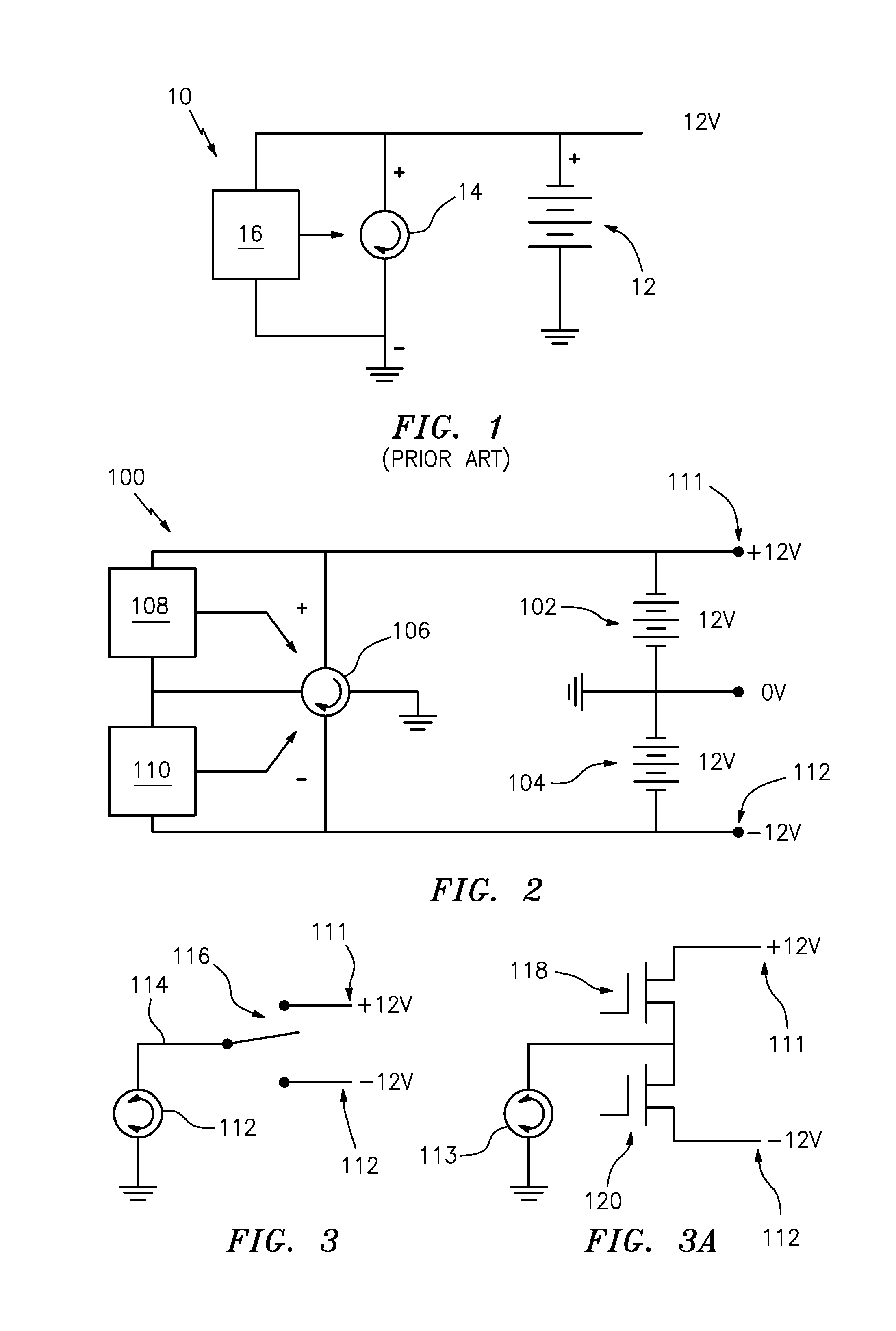
[0043]FIG. 1, labeled “Prior Art”, shows the common automotive electrical system 10 comprising: a single 12 V battery 12 electrically connected to an alternator 14 and a voltage control 16. It is unipolar.

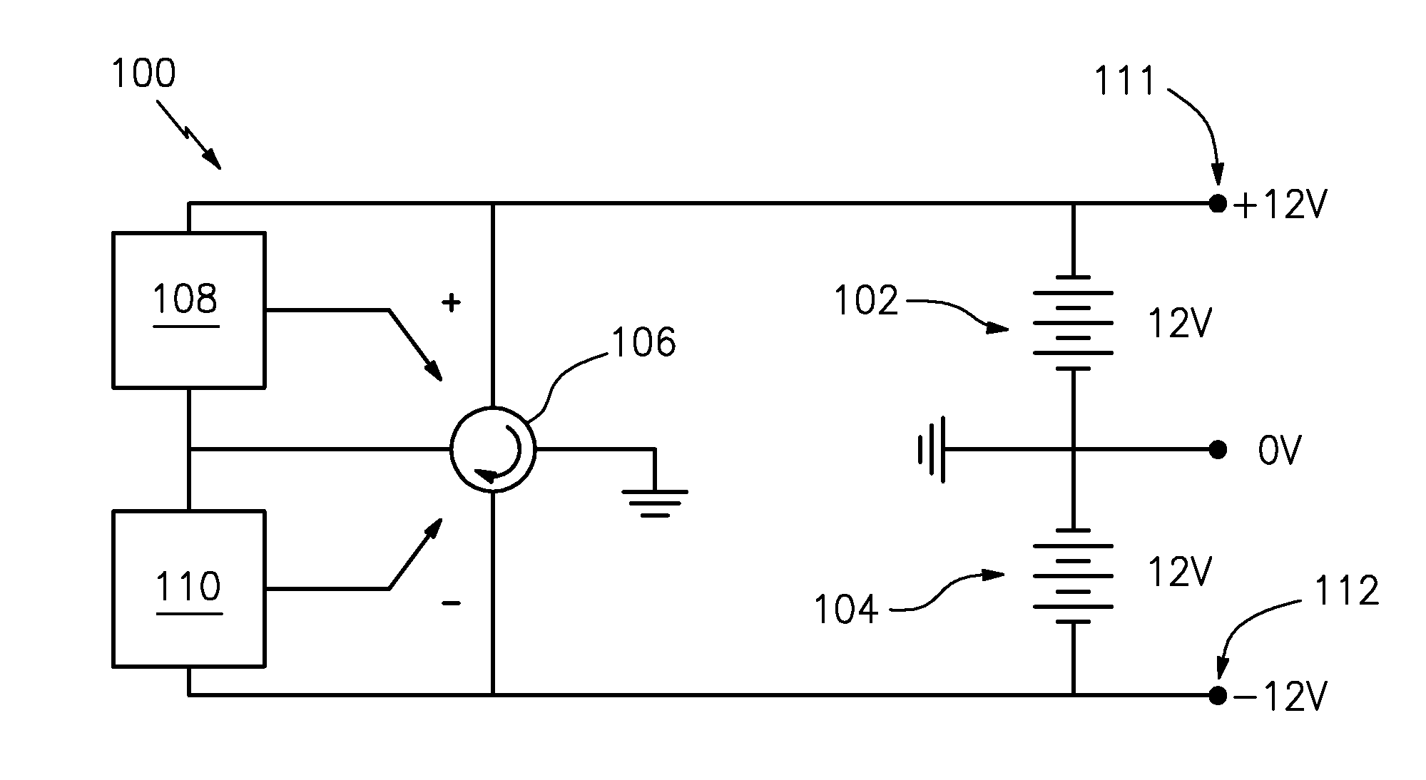
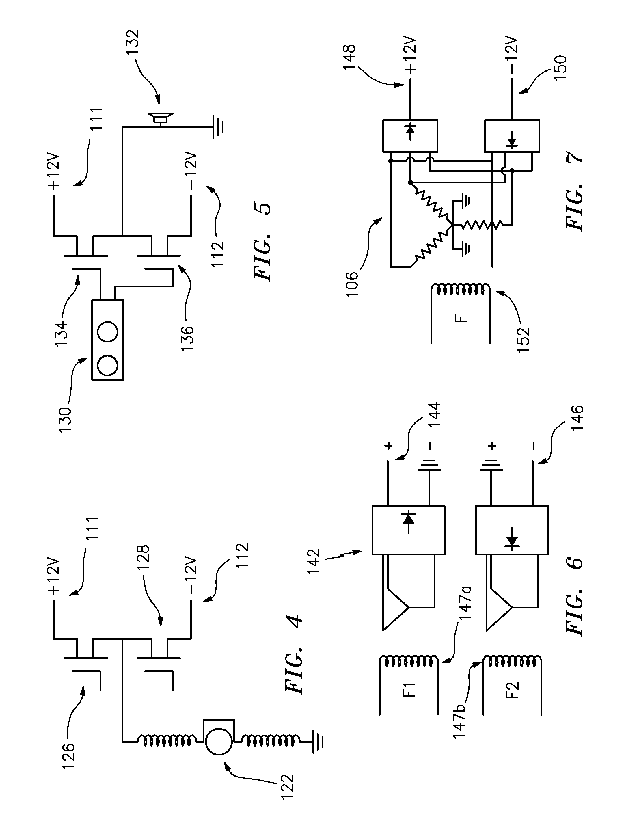
[0044]Referring to FIGS. 2-8 in detail, Applicant has disclosed a “Bipolar Automotive Electrical System”, both in apparatus and method form.

[0045]Applicant's invention can be thought of broadly, in “apparatus” terms, as a bipolar electrical system comprising an electrical circuit having: two (e.g., 12 V) batteries (e.g., 102, 104) of equal, but opposite voltage (e.g., +12 V, −12 V), in bipolar; a bipolar alternator (e.g., 106), with two opposite voltage outputs (i.e., plus and minus), responsive to the batteries (e.g., 102, 104) and controlling electrical charge to the batteries individually; two voltage controls (e.g., 108, 110), separately charging the two batteries (e.g., 102, 104); and wherein bipolar DC outputs (e.g., +12 V, −12 V) at 111, 112 from the batteries (e.g., 102, 1...


PUM


Abstract

Applicant has disclosed a method and apparatus for a bipolar automotive electrical system. In the preferred “apparatus” embodiment, Applicant's bipolar electrical system comprises: two (e.g., 12 V) batteries of equal, but opposite voltage (e.g., +12 V, −12 V), with bipolar outputs; an alternator, responsive to the batteries, which controls electrical charge to the batteries individually; an automotive DC motor connected by a single lead wire to the bipolar outputs from the batteries; and, wherein the reversible motor is run off the bipolar output without the need for any intervening devices between the bipolar command outputs and the motors. Alternatively, the alternator can inherently charge the batteries sequentially with the lowest voltage battery being addressed first. This approach allows heavy loads to be powered by 24 V or 48 V DC, yet the arc voltage to ground is still only 12 V or 24 V DC.

Description

FIELD OF THE INVENTION[0001]The present invention relates generally to power sources for vehicles and more particularly to electrical distribution systems to power automotive devices and systems.BACKGROUND OF THE INVENTION[0002]There has been growing dissatisfaction with the 12-volt battery currently used to power most automotive devices. Primarily there are two concerns: (a) the size of connected loads to the battery will grow in the future, e.g., with: (i) electric automotive air conditioning; (ii) using an electric motor to assist in acceleration and / or to actually launch a vehicle; (iii) high-power solid-state starting systems to enable “engine off” operation when stopped (i.e., to eliminate idling time); and (b) the difficulty of achieving high power, 1 HP or more at 12 V using semiconductors, due to heavy currents and the resulting high losses, especially when a semi-conductor bridge configuration is required (e.g., two active power devices in series, at currents of 75 A or mo...

Claims


Application Information

Patent Timeline
Patent Type & Authority Applications(United States)
IPC IPC(8): H02P7/14H02J7/14B60L1/00
CPCH02J7/1423Y02T10/7005Y02T10/648B60L11/1864Y02T10/7061B60L11/1853B60L58/18B60L58/21Y02T10/70Y02T10/64
Inventor GRADY, JOHN K.
Owner GRADY JOHN K
Why Eureka
Try Eureka