
Stent and method of forming a stent with integral barbs

a technology of stent and barb, which is applied in the field of medical devices, can solve the problems of inability to keep the targeted portion of the vessel from resting, blood vessels and ducts can occasionally weaken, and aneurysms can rupture, so as to reduce the likelihood of fracture, improve the likelihood of stress and strain, and improve the likelihood of barb fracture

Inactive Publication Date: 2012-09-06
COOK MEDICAL TECH LLC
View PDF1 Cites 21 Cited by
  • Summary
  • Abstract
  • Description
  • Claims
  • Application Information

AI Technical Summary

Benefits of technology

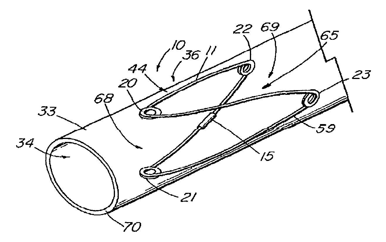
[0029]In yet another aspect of the invention, the valve includes a frame that is covered by a piece of biocompatible material, preferably an Extracellular Collagen Matrix (ECM) such as small intestinal submucosa (SIS) or another type of submucosa-derived tissue. Other potential biomaterials include allographs such as harvested native valve tissue. The material is slit or otherwise provided with an opening along one axis to form two triangular valve leaflets over a four-sided frame. In the deployed configuration, the leaflets are forced open by normal blood flow and subsequently close together in the presence of backflow to help eliminate reflux. Other configurations include a two-leaflet valve having an oval or elliptically shaped frame, and valves having three or more legs and associated leaflets, which provide a better distribution of the load exerted by the column of fluid acting on the leaflets.
[0044]In yet another aspect of the present invention, the stress-dispersing region of the barb comprises a coiled loop bend, U-shaped bend, or other series of bends distal to the point of attachment to add flexibility to the barb, thus reducing bending fatigue and the risk of barb fracture. The barb may include both a coiled loop bend (or other type of bend) and a free helical winding to add further flexibility.

Problems solved by technology

The functional vessels of human and animal bodies such as blood vessels and ducts can occasionally weaken.
For example, the aortic wall can weaken, resulting in an aneurysm.
Upon further exposure to haemodynamic forces, such an aneurysm can rupture.
For example, if an antistenotic stent migrates, it will fail to keep the targeted portion of the vessel from restenosing.
The aneurysm will then repressurize, presenting a risk of rupture.
Migration can be a significant problem in the placement of expandable stents and other intraluminal devices, especially when placed in the arterial region of the vascular system.
Nowhere is the prevention of migration more important and more challenging than when placing a stent graft to repair an abdominal aortic aneurysm (AAA) where downstream migration of the device can result in the aneurysm no longer being excluded.
If the aneurysm is no longer intact or subsequent rupture were to occur, the patient would then face an increased risk of death.
If this happens to a fenestrated thoracic endoluminal prosthesis, for example, important branch vessels (e.g. the common carotid) can be occluded, resulting in death.
If this happens to an aortic abdominal endoluminal prosthesis with renal artery fenestrations, kidney function can be seriously impaired.
However, barbs attached by these methods have been known to break off or bend because repeated physiological stresses, the cyclical loading caused by cardiovascular pulsatile forces in particular, cause mechanical fatigue and failure of the barb-stent junction.
It has been observed that sutures attaching barbed stents to the graft material are subject to breakage due in part to the flexibility of the graft material and the considerable pulsatile forces of arterial blood acting on the device.
If the barbs were bent in the manufacturing process, the barbs are further weakened.
Furthermore, the barbs are exposed to a physiological environment which is saline, oxygen-rich and acidic, and therefore tends to weaken the barb and its connection through corrosion.
It has also been further observed that barbs soldered or otherwise attached to the stent frame are subject to fracture, detachment, or other failure, especially when the forces become concentrated at a particular location along the stent graft.
Unfortunately, simply making the barbs stronger to prevent fracture can result in increased damage to the anchoring tissue.
Furthermore, adding rigidity to any outward-projecting barbs may compromise the ability of the device to be compressed and loaded into a delivery system.

Method used


Image

  • Stent and method of forming a stent with integral barbs
  • Stent and method of forming a stent with integral barbs
  • Stent and method of forming a stent with integral barbs

Examples


second embodiment

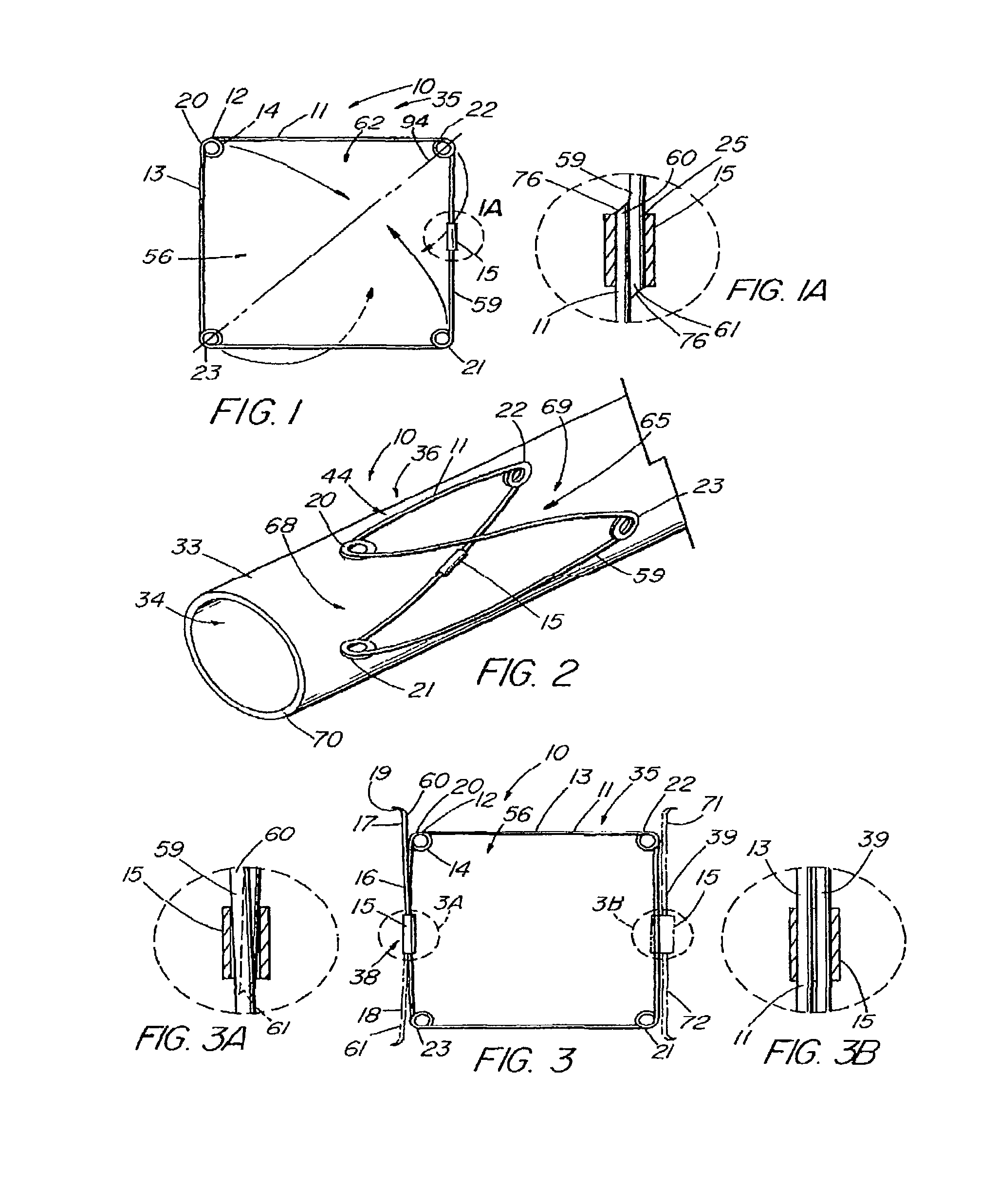
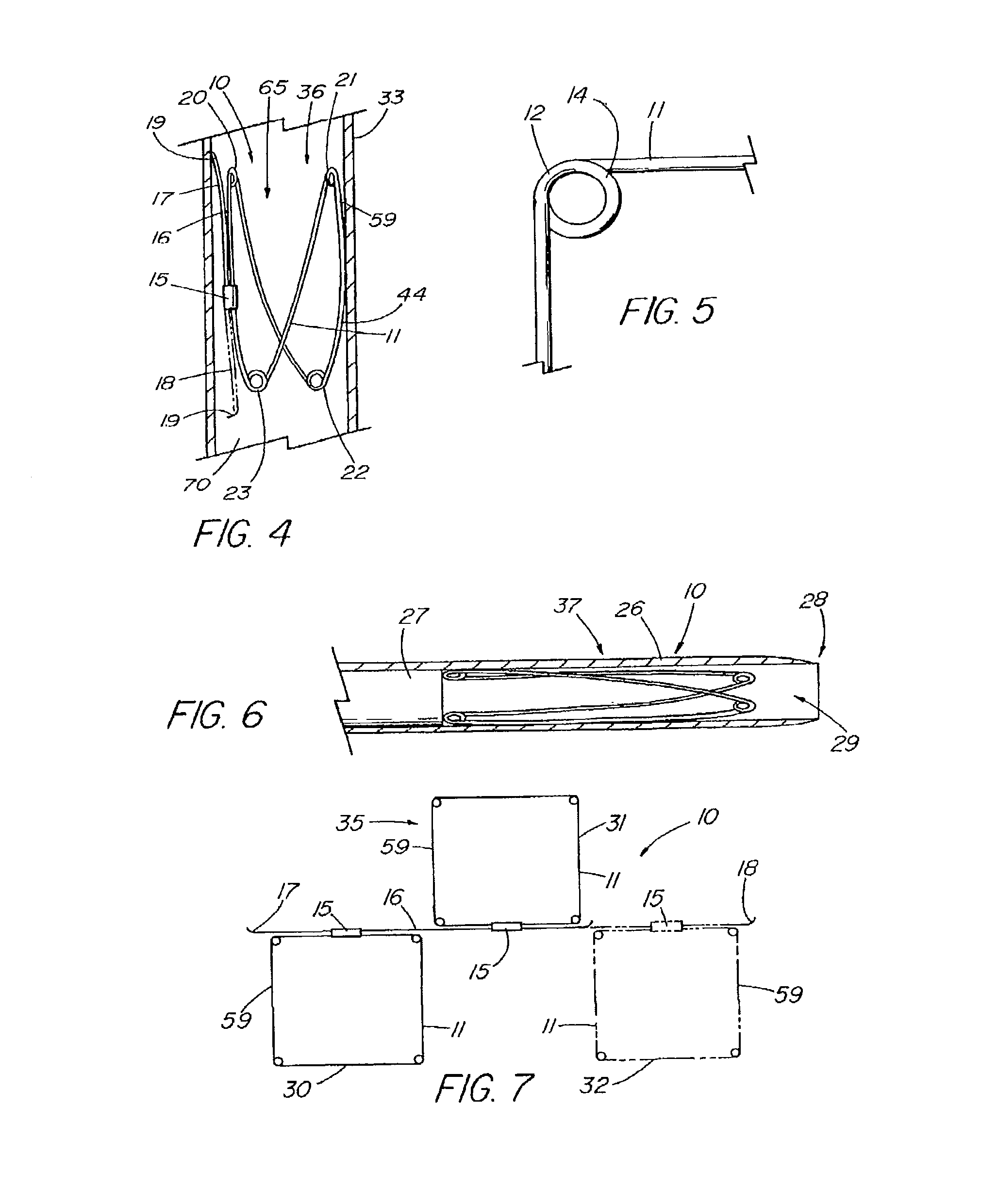
[0138]the present invention is depicted in FIG. 3 wherein one or more barbs 16 are included to anchor the device 10 following deployment. As understood, a barb can be a wire, hook, or any structure attached to the frame and so configured as to be able to anchor the device 10 within a lumen. The illustrative embodiment includes a first barb 16 with up to three other barbs 17,71,72, indicated in dashed lines, representing alternative embodiments. As depicted in detail view A of FIG. 3, the barb combination 38 that comprises barbs 17 and 18, each barb is an extension of the single piece 59 of material of the frame 11 beyond the closed circumference 59. The attachment cannula 15 secures and closes the single piece 59 of material into the frame 11 as previously described, while the first and second ends 60,61 thereof, extend from the cannula 15, running generally parallel with the side 13 of the frame 11 from which they extend, each preferably terminating around or slightly beyond respec...

third embodiment

[0140]FIG. 7 depicts a top view of the present invention in the first configuration 35 that includes a plurality of frames 11 attached in series. In the illustrative embodiment, a first frame 30 and second frame 31 are attached by a barb 16 that is secured to each frame by their respective attachment mechanisms 15. The barb 16 can be a double-ended barb 39 as shown in FIG. 3 (and detail view B) that is separate from the single pieces 59 comprising frames 30 and 31, or the barb may represent a long extended end of the one of the single pieces 59 as shown in detail view A of FIG. 3. Further frames, such as third frame 32 shown in dashed lines, can be added by merely extending the length of the barb 16. FIG. 8 depicts a side view of the embodiment of FIG. 7 in the second configuration 36 as deployed in a vessel 33.

fourth embodiment

[0141]FIGS. 12-18 depict embodiments of the present invention in which a covering 45 comprising a sheet of fabric, collagen (such as small intestinal submucosa), or other flexible material is attached to the frame 11 by means of sutures 50, adhesive, heat sealing, “weaving” together, crosslinking, or other known means. FIG. 12 depicts a top view of the present invention while in the first configuration 35, in which the covering 45 is a partial covering 58, triangular in shape, that extends over approximately half of the aperture 56 of the frame 11. When formed into the second configuration 36 as shown in FIGS. 13-14, the device 10 can act as an artificial valve 43 such as the type used to correct valvular incompetence. FIG. 13 depicts the valve 43 in the open configuration 48. In this state, the partial covering 58 has been displaced toward the vessel wall 70 due to positive fluid pressure or flow in a first direction 46, e.g., normal venous blood flow, thereby opening a passageway ...


PUM

PropertyMeasurementUnit
angleaaaaaaaaaa
angleaaaaaaaaaa
thickaaaaaaaaaa

Abstract

A method for manufacturing a barbed stent includes providing a sheet of stent material, cutting the sheet to form a stent wire with integral barbs extending therefrom, and forming the stent wire into a final stent shape having a longitudinal axis. A stent for deployment within the body of a patient includes integral barbs.

Description

CROSS-REFERENCE TO RELATED APPLICATIONS[0001]The present patent document is a continuation-in-part of application Ser. No. 10 / 431,809 filed May 8, 2003, which claims the benefit of the filing date under 35 U.S.C. §119(e) of Provisional U.S. Patent Application Ser. No. 60 / 381,046 filed May 16, 2002. All of the foregoing applications are hereby incorporated by reference.[0002]This present patent document also claims the benefit of the filing date under 35 U.S.C. §119(e) of Provisional U.S. Patent Application Ser. No. 60 / 403,783, filed Aug. 15, 2002, which is hereby incorporated by reference.[0003]This application is related to currently pending U.S. application “Implantable Vascular Device,” of Case, et al., filed concurrently Aug. 15, 2003, which is hereby incorporated by reference.TECHNICAL FIELD[0004]The present invention relates to medical devices and, in particular, a method of forming a stent for implantation within human or animal bodies for the repair of damaged vessels such a...

Claims


Application Information

Patent Timeline
Patent Type & Authority Applications(United States)
IPC IPC(8): B21D43/28C25F3/16B23K26/00H02G1/12B24B1/00A61F2/06A61F2/24A61F2/82A61F2/90
CPCA61F2/07A61F2230/0067A61F2/2475A61F2002/8483C25F3/24A61F2/848A61F2/89A61F2/90A61F2/915A61F2002/075A61F2220/005A61F2220/0058A61F2230/0095A61F2220/0016A61F2220/0075A61F2230/0026A61F2230/0058A61F2230/0091A61F2220/0008A61F2230/001A61F2230/0023A61F2230/0054A61F2/2418
Inventor OSBORNE, THOMAS A.MEAD, JASON A.
Owner COOK MEDICAL TECH LLC
Learn More