Fluorescence correlation spectroscopy system for analyzing particles in a medium
a technology of fluorescence correlation and particle analysis, which is applied in the direction of fluorescence/phosphorescence, luminescent dosimeters, optical radiation measurement, etc., can solve the problems of useless use of microscope lenses and passive substrates, and achieve the effect of low production costs and single-molecule sensitivity
- Summary
- Abstract
- Description
- Claims
- Application Information
AI Technical Summary
Benefits of technology
Problems solved by technology
Method used
Image
Examples
first embodiment
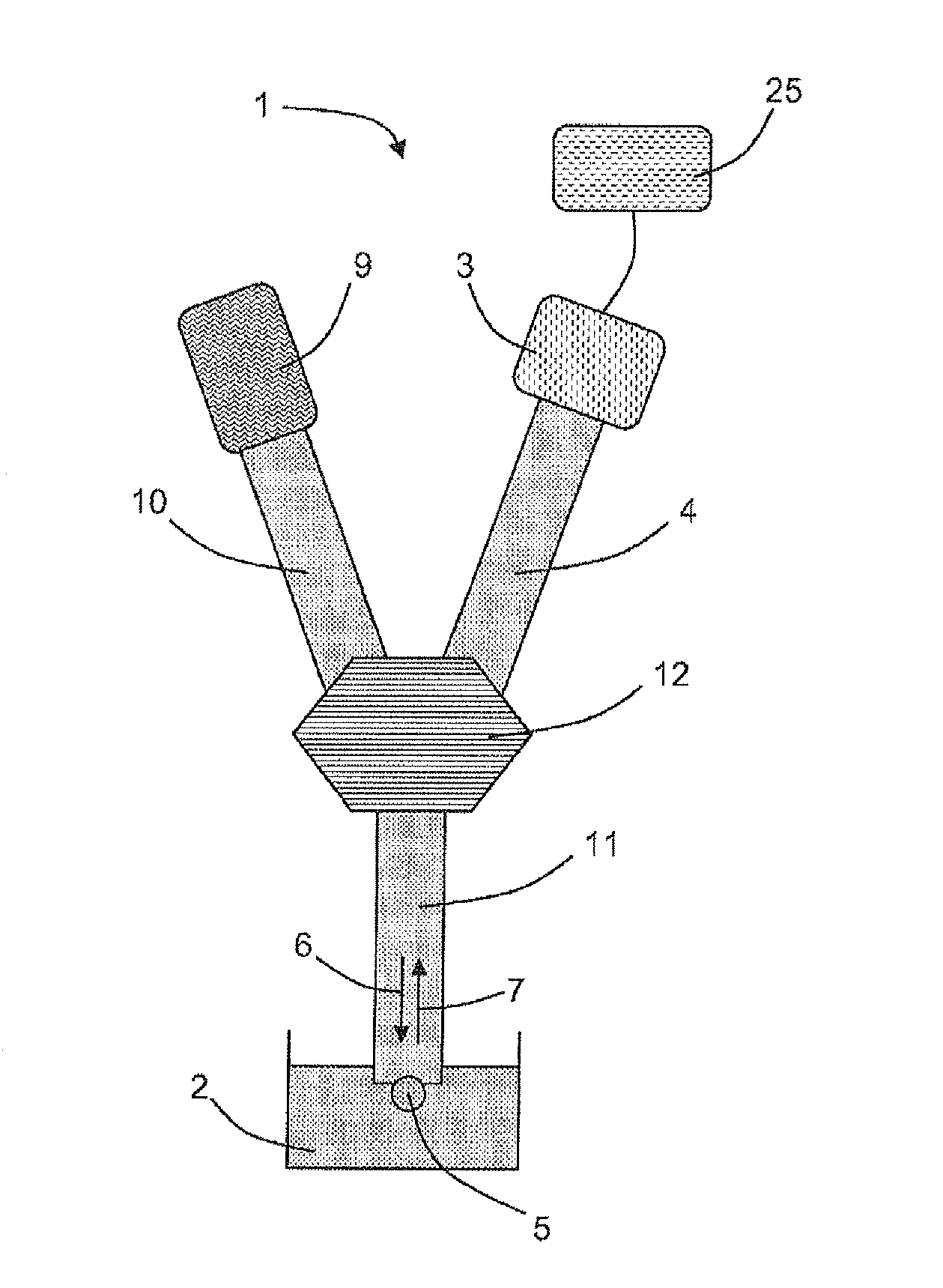
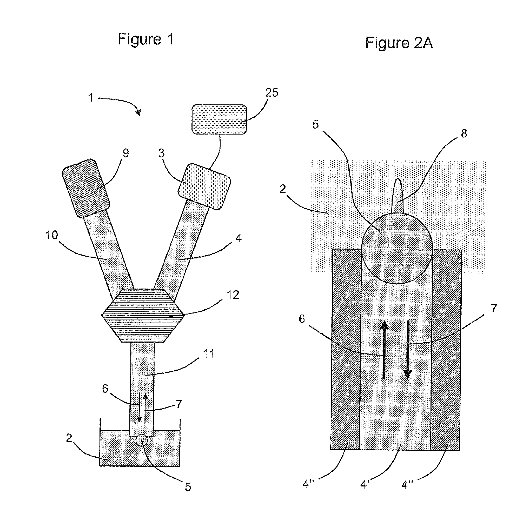
[0050]FIG. 1 represents a diagram of a spectroscopy system for analyzing particles in a medium according to the invention.
[0051]The purpose of the spectroscopy system 1 is to analyze a sample in a medium 2. This sample may be a liquid, gaseous medium or a biological object containing particles to analyze. The particles to analyze may be molecules or molecular assemblies, such as for example molecular complexes, nanocrystals or nanobeads.
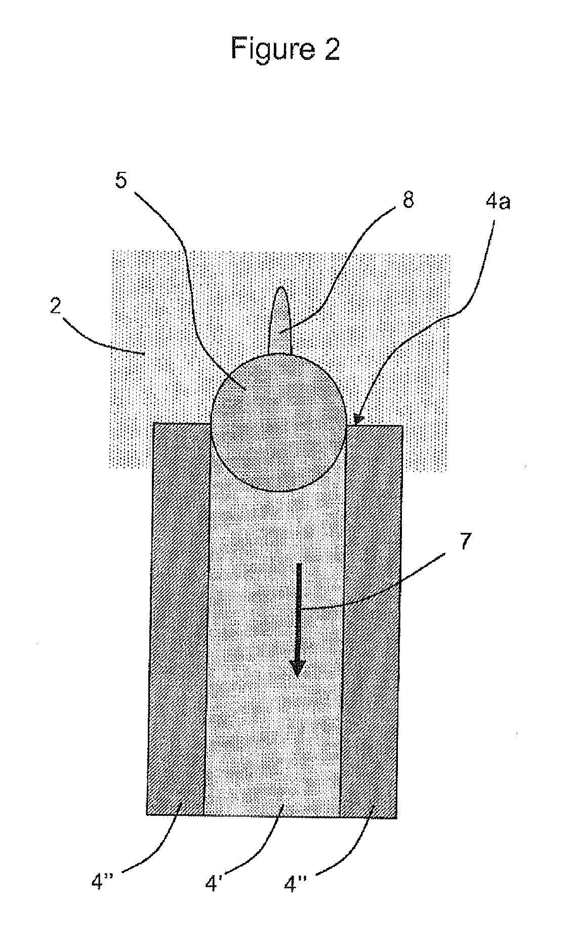
[0052]Therefore, the system 1 comprises a detection means 3, a waveguide 4 and a confinement means 5.
[0053]The detection means 3 makes it possible to measure the intensity of the light flux 7 emitted by the sample 2 at an observation volume and collected by the spectroscopy system 1. In a particular embodiment, this means 3 comprises photodetectors with electron amplifiers, advantageously photodiodes operating in avalanche regime—APD. These photodetectors may also be photomultipliers. According to other embodiments, this detection means 3 comprises o...
second embodiment
[0069]In the second embodiment, illustrated by FIG. 4, the system 1 is arranged to achieve fluorescence cross-correlation spectroscopy. For this reason, it comprises two illumination means 9′ and 9″, respectively emitting, via waveguides 10′ and 10″, excitation light beams 6′ and 6″, at different wavelengths λ′ and λ″. These beams 6′ and 6″ are mixed at a coupler 12′ to generate an excitation light beam 6, comprising two wavelengths, which is then injected into a guide 11′, then into a guide 11 via another coupler 12.
[0070]This beam 6 excites the particles of the medium 2 located in an excitation volume delimited by the confinement means 5.
[0071]The excited particles in this volume thus, emit a light beam 7 in response, by fluorescence, which is injected into the guide 11 thanks to the confinement means 5. This fluorescent light is transmitted to the guide 11′ via the coupler 12, then is spectrally separated at the coupler 12″, into two beams 7′ and 7″ respectively at wavelengths λ′...
third embodiment
[0073]In the third embodiment, illustrated by FIG. 5, the system is arranged to achieve fluorescence cross-correlation spectroscopy.
[0074]For this, it comprises two spectroscopy systems (or sub-systems) 1′ and 1″ identical to the embodiment of FIG. 1. These sub-systems respectively comprise an illumination means 9′ (or 9″), waveguides 4′10′ and 11′ (or 4″, 10″ and 11″), a coupler 12′ (or 12″), a detection means 3′ (or 3″) and a confinement means 5′ (or 5″).
[0075]The illumination means 9′ and 9″ are able to emit excitation light beams at a same excitation wavelength, via the waveguides 10′ and 11′ (10″ and 11″). The detection means 3′ and 3″ are able to detect the light 7′ and 7″ emitted by fluorescence by the particles in the medium 2, and are also coupled to a same means 26 for processing the signal that they provide. The processing treatment 26 thus, operates the cross-correlation of the data transmitted by the two detectors 3′ and 3″.
[0076]The two end pieces 11′ and 11″—as well a...
PUM
 Abstract
Description
Claims
Application Information
 - R&D
- Intellectual Property
- Life Sciences
- Materials
- Tech Scout
- Unparalleled Data Quality
- Higher Quality Content
- 60% Fewer Hallucinations
Browse by: Latest US Patents, China's latest patents, Technical Efficacy Thesaurus, Application Domain, Technology Topic, Popular Technical Reports.
© 2025 PatSnap. All rights reserved.Legal|Privacy policy|Modern Slavery Act Transparency Statement|Sitemap|About US| Contact US: help@patsnap.com


