Spectroscopic sensor and angle limiting filter

a technology of angle limitation and spectroscopic sensor, which is applied in the direction of spectrometry/spectrophotometry/monochromators, instruments, optical radiation measurement, etc., can solve the problem of difficult to reduce the size, difficult to install a number of sensors at desired places or constantly install sensors, and the possibility of making it difficult for light to have an incident angle exceeding the limited angular rang

Active Publication Date: 2012-09-20
SEIKO EPSON CORP
View PDF2 Cites 15 Cited by
  • Summary
  • Abstract
  • Description
  • Claims
  • Application Information

AI Technical Summary

Benefits of technology

[0010]According to the aspect, an optical path is formed by the light shielding layers, whereby a minute pattern can be formed, and the angle limiting filter reduced in size can be manufactured. Moreover, in the region surrounding the first light-shielding layer and the region surrounding the third light-shielding layer, the second light-shielding layer and the fourth light-shielding layer are provided, respectively. Therefore, the angle limiting filter having high surface planarity can be manufactured.
[0012]According to this configuration, it is possible to prevent light from passing between the first light-shielding layer and the second light-shielding layer, and between the third light-shielding layer and the fourth light-shielding layer. Moreover, when these light-shielding layers are conductors, electrical conductivity can be obtained between these light-shielding layers.
[0014]According to this configuration, since the edge surface of the second light-shielding layer is located at the center of the width of the second portion of the first light-shielding layer, it is possible to prevent the second light-shielding layer from exposing in the optical path. Moreover, when these light-shielding layers are conductors, electrical conductivity can be obtained more reliably between these light-shielding layers.
[0019]According to this configuration, the light shielding layers are configured with a substance having a low light reflectance, whereby it is possible to reduce light incident on a wall surface of the optical path to pass through the optical path. Accordingly, even with the angle limiting filter reduced in size, it is possible to make at difficult for light having an incident angle exceeding the limited angular range to pass through the optical path.

Problems solved by technology

However, a related-art spectroscopic sensor has a problem that it is difficult to reduce the size thereof.
Therefore, it is difficult to install a number of sensors at desired places or constantly install sensors.
Accordingly, even with the angle limiting filter reduced in size, it is possible to make at difficult for light having an incident angle exceeding the limited angular range to pass through the optical path.

Method used


Image

  • Spectroscopic sensor and angle limiting filter
  • Spectroscopic sensor and angle limiting filter
  • Spectroscopic sensor and angle limiting filter

Examples


first embodiment

1. First Embodiment

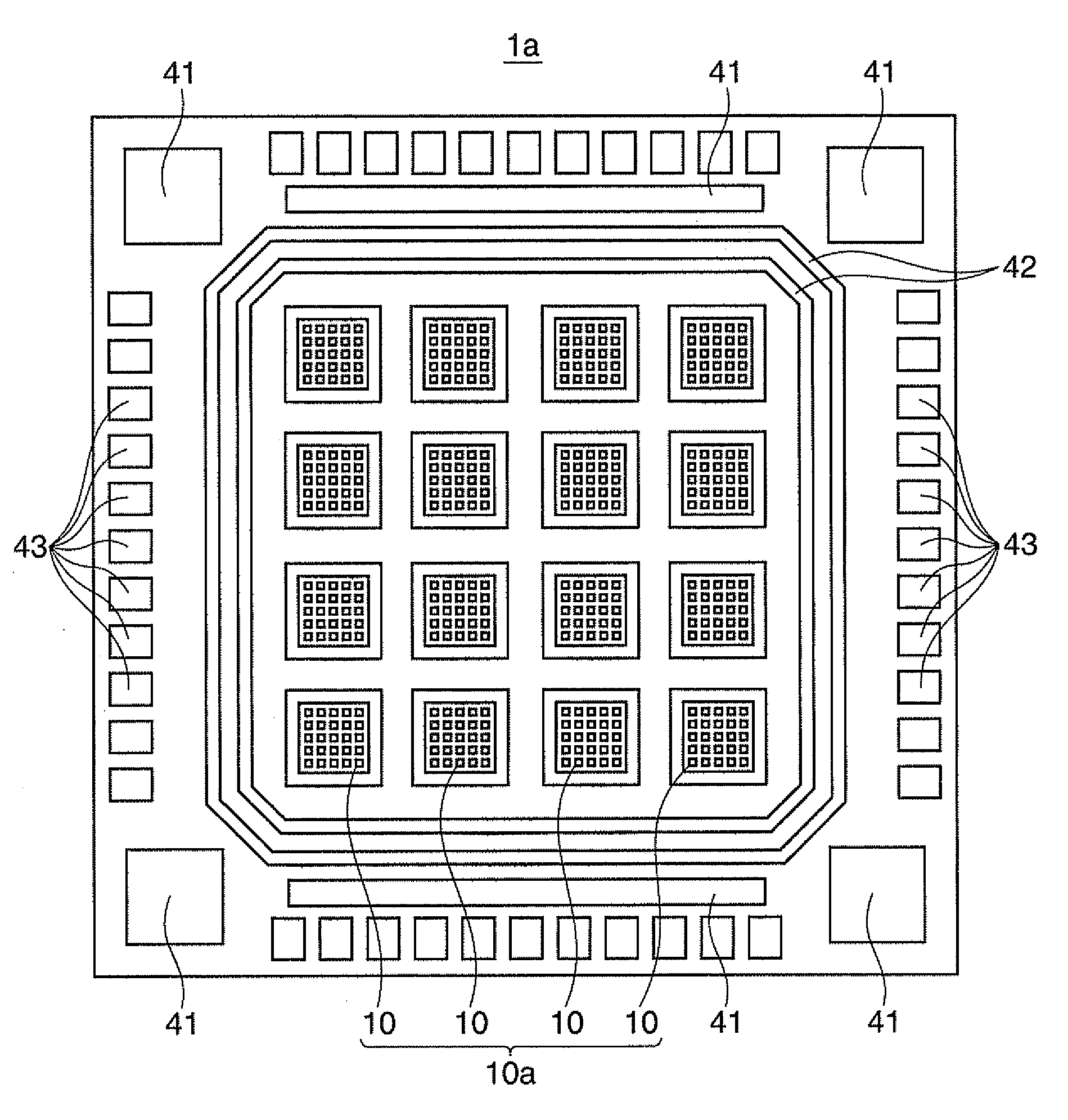
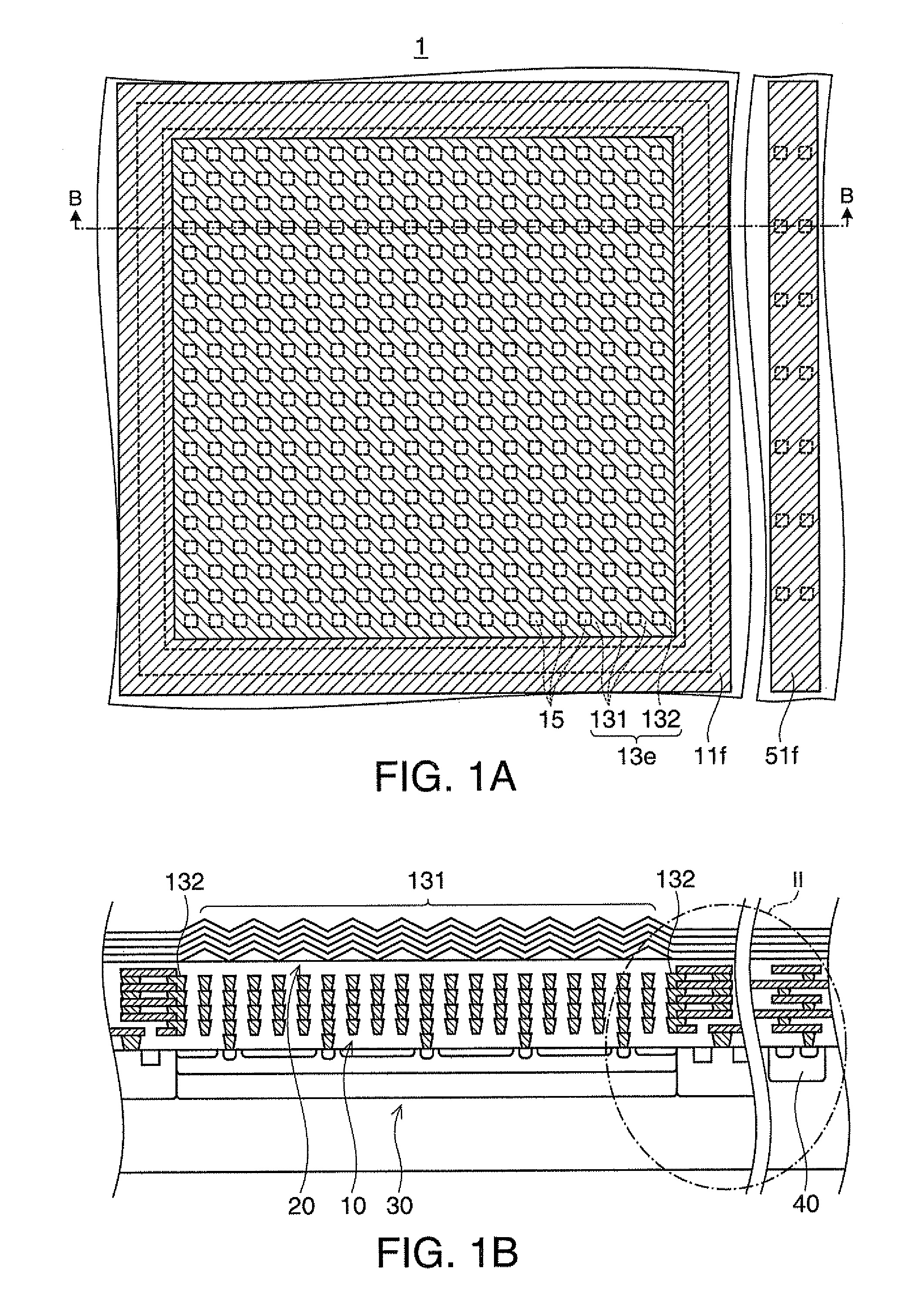
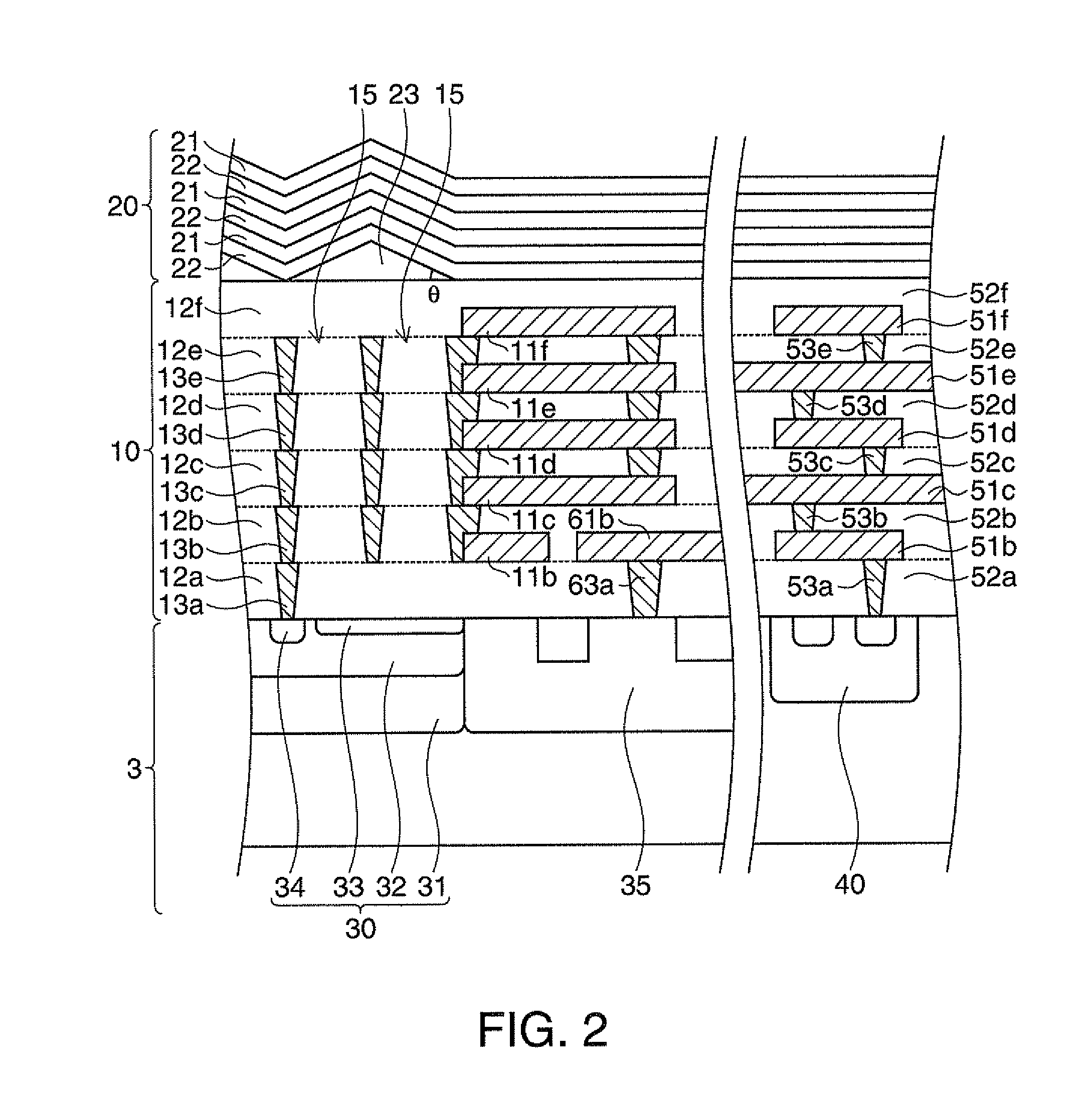
[0034]FIGS. 1A and 1B are schematic views showing an angle limiting filter and a spectroscopic sensor according to a first embodiment of the invention. FIG. 1A is a plan view of the spectroscopic sensor. FIG. 1B is a cross-sectional view taken along line B-B of FIG. 1A, FIG. 2 is a cross-sectional view showing the angle limiting filter and the spectroscopic sensor according to the first embodiment. FIG. 2 corresponds to an enlarged view of a portion of surrounding line II shown in FIG. 1B.

[0035]The spectroscopic sensor 1 includes the angle limiting filter 10, a wavelength limiting filter 20, and a light receiving element 30 (refer to FIG. 1B). In FIG. 1A, the wavelength limiting filter 20 is not illustrated.

[0036]In a P-type silicon substrate 3 (refer to FIG. 2) as a semiconductor substrate on which the spectroscopic sensor 1 is formed, an electronic circuit including semiconductor elements 40 which apply a predetermined reverse bias voltage to the light receiving...

second embodiment

2. Second Embodiment

[0077]FIG. 4 is a cross-sectional view partially showing an angle limiting filter and wiring layers according to a second embodiment of the invention.

[0078]In the second embodiment, the thickness of the aluminum alloy layer 11e (and 11f) is greater compared to that of the aluminum alloy layers 11b to 11d. In such a case, for connecting the tungsten layer 13e with the tungsten layer 13d below the tungsten layer 13e when a groove is formed in the silicon oxide layer 12e to embed the tungsten layer 13e into the groove, it is necessary to make the groove formed in the silicon oxide layer 12e deep. However, if the etching time for the silicon oxide layers 12e and 52e is extended when the formation of groove in the silicon oxide layer 12e and the formation of groove in the silicon oxide layer 52e are performed in a common process, a titanium nitride (TiN) film on a surface of the aluminum alloy layer 51e is etched. Therefore, an electrical resistance between the alumin...

third embodiment

3. Third Embodiment

[0082]FIG. 5 is a cross-sectional view partially showing an angle limiting filter and wiring layers according to a third embodiment of the invention.

[0083]In the third embodiment, an aluminum alloy layer is not formed on the silicon oxide layer 12e and the uppermost tungsten layer 13e. In the first embodiment, since the aluminum alloy layer 11f is formed on the silicon oxide layer 12e and the tungsten layer 13e, and the silicon oxide layer 12f is further formed on the aluminum alloy layer 11f, it is necessary to planarize the silicon oxide layer 12f after depositing the silicon oxide layer 12f. In contrast to this, in the third embodiment, since an aluminum alloy layer is not formed on the silicon oxide layer 12e and the uppermost tungsten layer 13e, but the silicon oxide layer 12f is formed thereon, the silicon oxide layer 12f is evenly formed only by depositing the silicon oxide layer 12f. Accordingly, in the third embodiment, the process of planarizing the sili...


PUM

PropertyMeasurementUnit
refractive indexaaaaaaaaaa
total thicknessaaaaaaaaaa
lengthaaaaaaaaaa

Abstract

An angle limiting filter includes: a first light-shielding layer containing a first light-shielding material and provided with a first opening; a second light-shielding layer containing a second light-shielding material and located in a region which surrounds at least one portion of the first light-shielding layer; a third light-shielding layer containing the first light-shielding material, provided with a second opening at least one portion of which overlaps the first opening, and located above the first light-shielding layer; and a fourth light-shielding layer containing the second light-shielding material and located above the second light-shielding layer in a region which surrounds at least one portion of the third light-shielding layer.

Description

[0001]The entire disclosure of Japanese Patent Application No. 2011-059232, filed Mar. 17, 2011 and No. 2012-015047, filed Jan. 27, 2012 are expressly incorporated by reference herein.BACKGROUND[0002]1. Technical Field[0003]The present invention relates to a spectroscopic sensor and an angle limiting filter.[0004]2. Related Art[0005]In the fields of medical care, agriculture, environment, and so on, spectroscopic sensors are used for diagnosing and inspecting objects. For example, in the field of medical care, a pulse oximeter is used to measure the blood oxygen saturation level using light absorption by hemoglobin. In the field of agriculture, a saccharometer is used to measure the sugar content of fruits using light absorption by sugar.[0006]JP-A-6-129908 discloses a spectroscopic imaging sensor which limits the incident angle with an optical fiber optically connecting between an interference filter and a photoelectric conversion element to thereby limit the transmission wavelengt...

Claims


Application Information

Patent Timeline
Patent Type & Authority Applications(United States)
IPC IPC(8): G01N21/55G02B27/00
CPCG01J3/0256G01J2003/1226G01J3/36G01J3/0289H01L27/1462H01L27/14623G01J3/0205G01J3/28G02B5/20
Inventor NAKAMURA, NORIYUKI
Owner SEIKO EPSON CORP
Why Eureka
Try Eureka