Flexible sensing material containing carbon nanotubes

a carbon nanotube and sensing material technology, applied in the field of sensors, can solve the problems of reducing the elastomeric properties of bulk materials, not working well in thin film applications, and reducing the conductivity of bulk materials, so as to increase the conductivity and reduce the effect of conductivity

Active Publication Date: 2012-10-11
COVESTRO LLC
View PDF3 Cites 40 Cited by
  • Summary
  • Abstract
  • Description
  • Claims
  • Application Information

AI Technical Summary

Benefits of technology

[0079]Above the force sensor cells in FIG. 10 is thermistor 41 connected to silver circuit traces 40 and 42 silver screen printed on film 17 from the pattern of FIG. 18 as Film 3 Layer 1. The thermistor is preferably connected with silver epoxy and encapsulated with a tough flexible elastomeric resin for strain relief.
[0080]Detailed in FIG. 21 is a moisture sensor screen printed as two silver circuit traces forming two juxtaposed comb circuits 33 and 51 on film 17 from the screen pattern of FIG. 21 as Film 3 Side B Layer 1. A thin aqueous polyurethane dispersion shown as 47 in FIGS. 9 and 10 is applied over the top of the comb traces. Moisture will penetrate the polyurethane layer deposited over the comb circuits and increase the conductivity between the two comb circuits. In Example 2, a variation of the moisture sensor is disclosed where by the aqu

Problems solved by technology

When a force is applied to compress the material the particles touch and increase the number of conductive paths through the bulk material thereby decreasing the resistance of the material.
The change in resistance is a bulk material effect and not a surface effect, and as such does not work well in thin film applications.
Additionally, the high loadings of conductive particles in the elastomeric material will reduce the elastomeric properties of the bulk material.
Such high loadings of filler will reduce the physical properties of the resin binder, such as flexibility.
The substrate films of Maness et al. can conform to a two dimensional surface but cannot conform to a three dimensional surface well without creasing.
The substrate

Method used


Image

  • Flexible sensing material containing carbon nanotubes
  • Flexible sensing material containing carbon nanotubes
  • Flexible sensing material containing carbon nanotubes

Examples


example 1

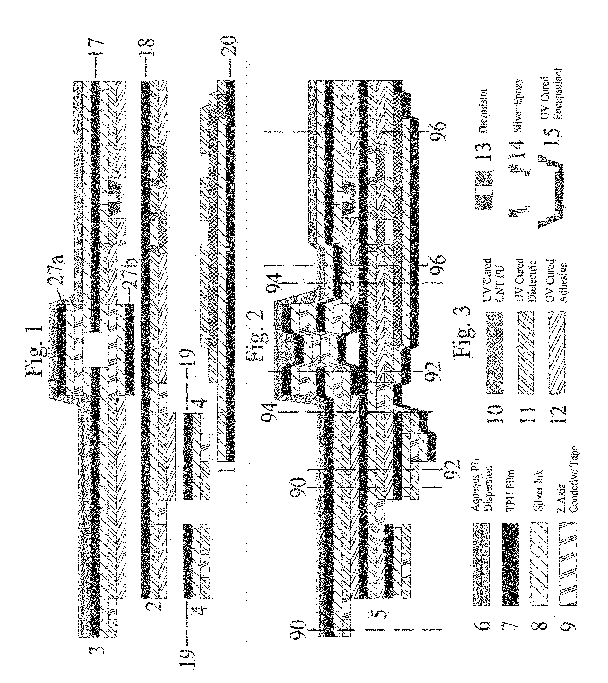
[0084]Three films of 5 mil THERMOPLASTIC POLYURETHANE, measuring 19″×23.5″ were dry laminated onto ALUMINUM SHEETS for support during the screen printing process.

[0085]Using the art work in FIGS. 11 through 21 (minus the number indicators added for clarity of the Detailed Description of Invention), each film was printed using polyester screens of mesh size, ink and layer order as noted on the Figures.

[0086]The FLEXIBLE SILVER INK was cured for 10 minutes at 110° C.

[0087]UV CURED CNT CONDUCTIVE INKs were cured with the following UV exposure.

[0088]UVA 249 mJ / cm2

[0089]UVB 210 mJ / cm2

[0090]UVC 60 mJ / cm2

[0091]UVV 185 mJ / cm2

[0092]Film 3 Side B of FIG. 21 was printed first. The film was then turned over and Side A layers of FIGS. 18 to 20 were printed leaving the film ready for mounting the THERMISTORS. THERMISTORS were mounted on the eight pad sets beginning with pads 42 and 40 on Film 3 Side A using CONDUCTIVE SILVER EPOXY and cured for 24 hours.

[0093]Two holes 3 / 16″ diameter and cent...

example 2

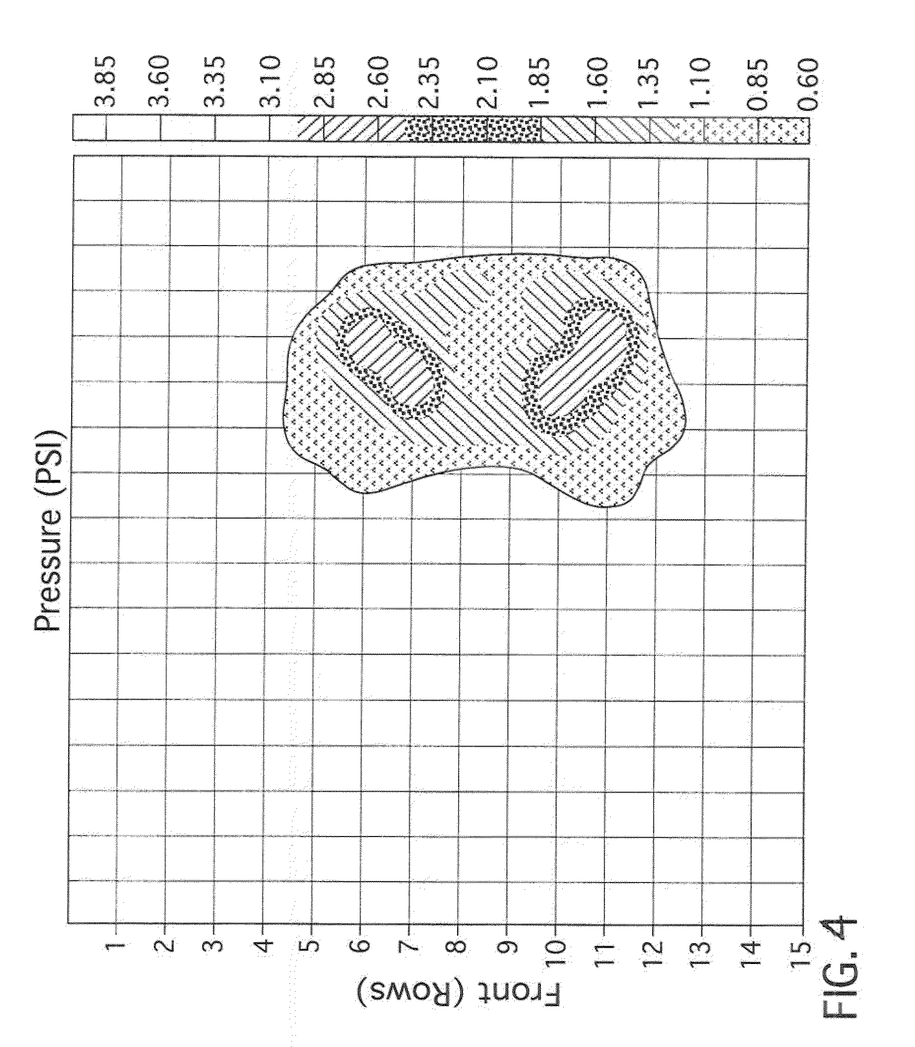
[0105]A strip 3 / 16″×1″ of the UV CURED CNT CONDUCTIVE INK was printed between two electrodes and exposed to varying levels of humidity. As the humidity increased the resistance of the strip increased.


PUM

PropertyMeasurementUnit
Fractionaaaaaaaaaa
Diameteraaaaaaaaaa
Diameteraaaaaaaaaa

Abstract

The present invention relates to a flexible sensing material made from (a) at least one flexible polymeric layer and (b) at least one conductive, curable coating layer containing about 0.01 wt. % to about 5 wt. % of multi-walled carbon nanotubes having a diameter of greater than about 4 nm, about 10 wt. % to about 99 wt. % of an aliphatic urethane acrylate and about 0.1 wt. % to about 15 wt. % of a photoinitiator, wherein the weight percentages are based on the weight of the formulation, wherein the coating layer is curable by exposure to radiation and wherein the cured coating layer has a surface resistivity of about 102Ω/□ to about 1010Ω/□. The inventive sensing material may prove useful for sensing one or more of pressure, temperature and moisture and find use in a wide variety of applications.

Description

STATEMENT REGARDING FEDERALLY SPONSORED RESEARCH[0001]This invention was made at least in part, through research funded by the U.S. Government under contract number FA 8650-06-3-9000 awarded by the U.S. Air Force Research Laboratory, USAF. The government may have certain rights in the invention.FIELD OF THE INVENTION[0002]The present invention relates in general to sensors and more specifically to a flexible, multi-layered sensing material for measuring one or more parameters such as pressure, temperature and moisture. The inventive sensing material includes one or more a flexible layers and an ultraviolet (UV) curable coating layer containing conductive carbon nanotubes.BACKGROUND OF THE INVENTION[0003]Since the discovery of carbon nanotubes in 1991 by Iijima, Nature, 354, pp. 56-58 (1991), extensive research has been carried out involving the synthesis, chemistry, and manipulation of these materials. Carbon nanotubes are electrically conductive along their length, chemically stabl...

Claims


Application Information

Patent Timeline
IPC IPC(8): B32B27/04C08F2/50B05D3/06B82Y30/00
CPCB82Y30/00G01L1/205H05K2201/0323H05K1/167H05K2201/026H05K1/0393Y10T428/24995
Inventor HUNT, ROBERT N.WILLIAMS, CHARLES TODD
Owner COVESTRO LLC
Why Eureka
Try Eureka