
Continuous thermal insulation and fire protective composite placed on thermo-grid designed for wind load transfer

a composite and thermal insulation technology, applied in the field of construction materials, can solve the problems of affecting the degree of fire protection, the cracking of the outer surface layer of the material, and the cracking of the 3-coat portland cement plaster, etc., and achieves the effect of easy modification, easy application, and even exterior surfa

Inactive Publication Date: 2012-12-20
BOMBERG MARK +1
View PDF57 Cites 30 Cited by
  • Summary
  • Abstract
  • Description
  • Claims
  • Application Information

AI Technical Summary

Benefits of technology

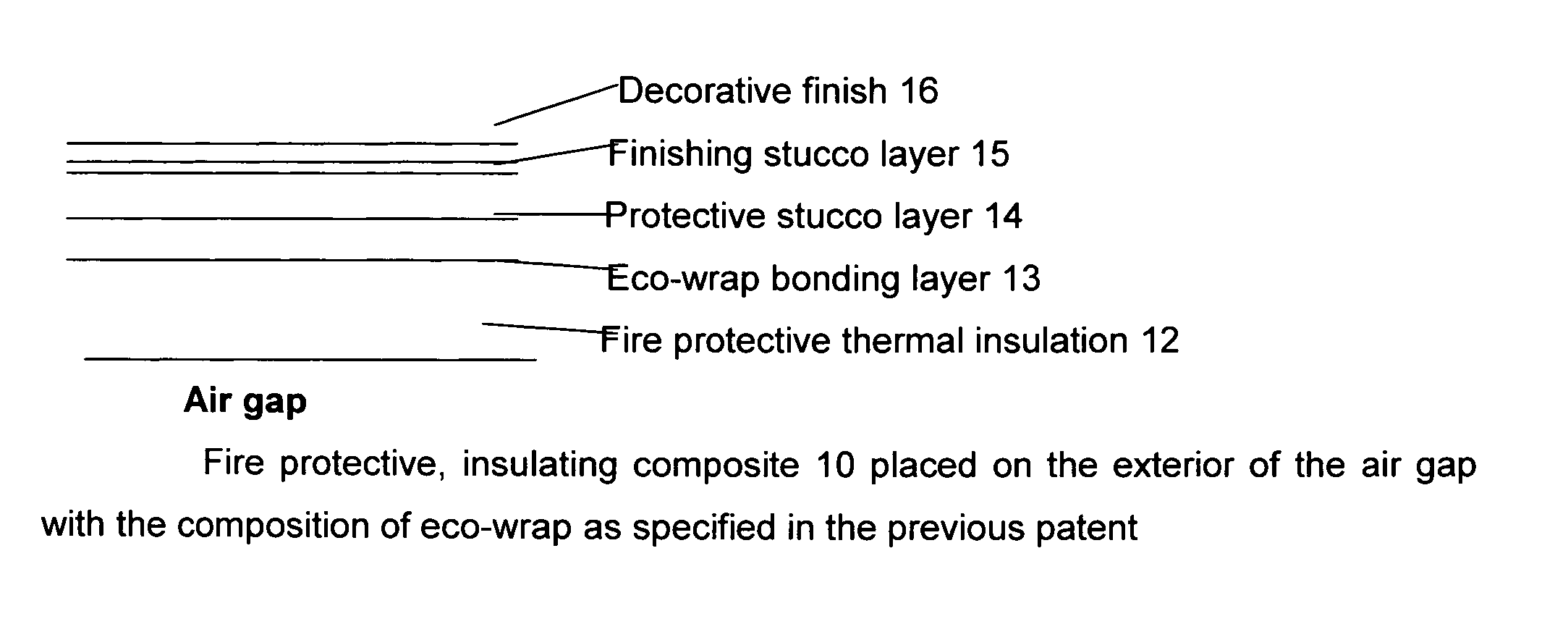
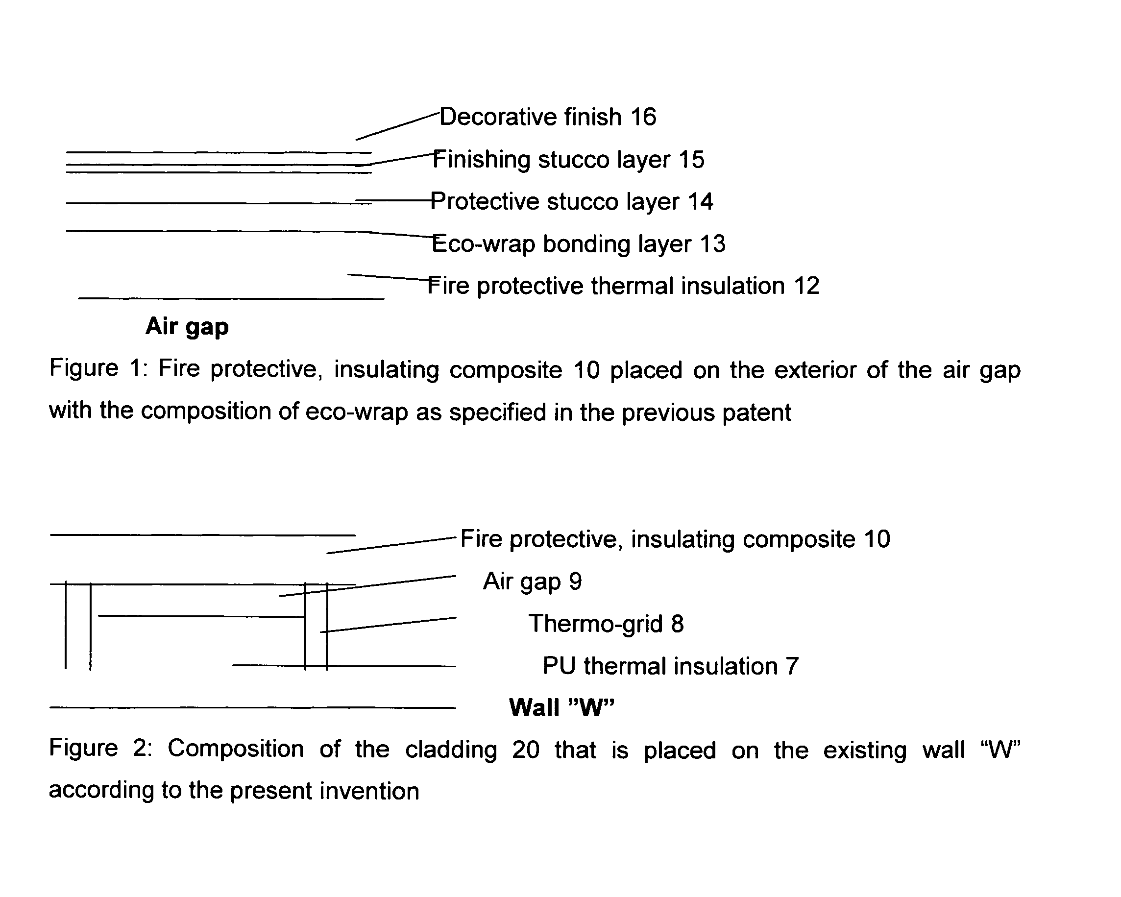
[0009]It is an object of the present invention, to provide a novel climatic stucco on continuous fire protective composite insulation that may be separated by an air gap from another continuous layer of thermal insulation to create a wall arrangement that will overcome typical problems of the prior art. It is a further object and advantage of the present invention to provide an insulated cladding system for new buildings, or retrofit to existing buildings that provides adequate rain water absorption, storage and accelerated water removal capability. While the previous invention dealt with the layered system in which each layer was different but homogenous in direction parallel to wall surface, this invention introduces structural members positioned in the direction perpendicular to the layers called here thermo-grid that carry the mechanical loads while allowing continuity of thermal insulation.
[0010]It is a further object of the present invention, to provide a climatic stucco wall construction which will prevents the entry of water into the existing wall surface and allow drying of water that accidentally entered into the wall structure say at wall-window interface.
[0011]It is still yet a further object of the present invention, to provide a climatic stucco construction arrangement which is easily applied, readily modified to accommodate variations in the existing wall's characteristics, and permit an even exterior surface for subsequent coat applications.
[0012]It is yet still a further object of the present invention to provide a climatic stucco construction arrangement that is fast, easily applied, energy efficient, strong and which is designed with consideration of the climatic conditions of the region and one that will outlast the prior art stucco construction by many years.
[0013]This invention is applicable to thermal upgrade of any existing wall or new construction by providing two layers of continuous exterior insulation and addressing heat, air and moisture control of the upgraded wall as well as increased fire protection for wood frame walls. Other objects and advantages of the present invention will in part be apparent, and in part appear hereinafter.OBJECTS AND ADVANTAGES OF THE PRESENT INVENTION
[0014]It is a principal object and advantage of the present invention to provide an external insulating cladding system and a process of construction of that insulating system onto a wall, leading to an assembly for that accelerates drainage and drying of moisture encapsulated during construction of the building or the building enclosure.

Problems solved by technology

Typical problem with a prior art is that joints between the adjacent boards may induce cracking in the outer surface layers of material if those boards are not installed tightly against one another and the wall.
Furthermore the degree of fire protection is limited and in many countries those systems are not allowed on high-rise-buildings.
Yet the 3-coat Portland Cement Plaster is prone to cracking and subsequent moisture penetration.
On the other hand, “synthetic stucco” (a thin lamina reinforced with fiberglass mesh) is elastic and less prone to cracking but it does not provide sufficient fire protection and drying ability to the wall as well.
It also lacks the “moisture storage capacity” of the traditional 3-coat lime-cement stucco.

Method used


Image

  • Continuous thermal insulation and fire protective composite placed on thermo-grid designed for wind load transfer
  • Continuous thermal insulation and fire protective composite placed on thermo-grid designed for wind load transfer

Examples


example 1

An External Insulation System for Cold Climate

[0042]Since 1994 flexible and rigid wood-fiber insulation boards have been produced in Germany in accordance with a standard WF-EN 13171-T3-CS (10 / Y) 20-TR7, 5-WS2, 0-MU5-AF100. When a multi-fiber system is used as an additive to the wood fibers to modify its physical properties this product is known as “Eco-fiber board”. The material came from Homatherm GmbH in Berga, Germany. It has density about 140 kg / m3, a thermal conductivity measured at 10° C. equal to 0.037 W / mK or thermal resistivity of 3.75 (of hr ft2) / BTU in, specific heat 2100 J / (kgK) and thickness 40 mm (1⅝ inch). It was mechanically fastened to thermo-grid using epoxy covered screws and plastic washers The HT wrap (the layers 13 and 14) was from a pilot production of Sto Corp with the mix was designed in accordance with this invention. Glass fiber mesh (5 oz) was placed between the layers 13 and 14. The layer 15 was a StoSilco®Lastic—a ready-mixed, silicone-enhanced, smooth...

example 2

External Insulation System for Warm Climate

[0043]There was no air gap in is example but a poured close cell polyurethane foam was applied with 2 ft increments between thermo-grid placed on each stud and serving as locations of the mechanical fasteners for the protective composite. In the actual example foams from two different manufacturers were used. One of the foams had CCMC 12840-Report that describes the technical features as follows: The final cured product has a nominal density of 30.4 kg / m3 and an assigned design thermal resistance of 1.05 m2·° C. / W per 25 mm (R6 per inch). Compressive strength is 222 kPa and tensile strength 337 kPa that is sufficient to ensure adhesion to the substrate and cohesion of the foam.

[0044]In this example, the HT wrap had additional admixture of layered silica to reduce its WVT and the finishing layer applied on an HT-wrap was acrylic coating with permeance below 1 perm.

Notes on the Examples of this Invention

[0045]This system has several options t...


PUM

PropertyMeasurementUnit
Permeabilityaaaaaaaaaa
Thermal propertiesaaaaaaaaaa

Abstract

The present invention relates to construction materials and more specifically, to a continuous composite exterior insulation system and cladding used in the construction of building walls and structure, to control heat transfer, rain-water penetration, air and water vapor transmission while providing fire protection to a building enclosure. This invention relates to a thermal upgrade of existing and new buildings. The wall substrate is arranged for receipt of subsequent layers of cladding materials. Thermo-grid of insulated composite strapping is mounted on the surface of the said wall and a layer of continuous insulation e.g. polyurethane foam is applied between the thermo-grid strapping leaving a thin air gap between it and the next layer of the fire protective composite.

Description

BACKGROUND OF THE INVENTION[0001]1. Field of the Invention[0002]The present invention relates to construction materials and more specifically, to a continuous composite exterior insulation system and cladding used in the construction of building walls and structure, to control heat transfer, rain-water penetration, air and water vapor transmission while providing fire protection to a building enclosure. This invention relates to a thermal upgrade of existing and new buildings and extends the utility patent (exterior building wall Insulation System with Hygrothermal Wrap application Ser. No. 12 / 807,730 by Bomberg that was based upon Provisional Patent Application Ser. Nos. 61 / 342,513 filed 15 Apr. 2010, 61 / 399,497 filed 13 Jul. 2010, and 61 / 520,871 filed 20 Jun. 2011, each being incorporated herein by reference in their entirety. The wall substrate is arranged for receipt of subsequent layers of cladding materials. Thermo-grid of insulated composite strapping is mounted on the surfac...

Claims


Application Information

Patent Timeline
IPC IPC(8): E04B1/94B32B38/16B32B37/14
CPCB32B37/02E04B1/762E04B1/94B32B2266/08B32B2305/022B32B2607/00B32B2307/304B32B2307/3065B32B2307/724B32B2307/7265B32B2309/105B32B2305/22
Inventor BOMBERG, MARKBOMBERG, NICOLE
Owner BOMBERG MARK
Learn More