Reversible polarity operation and switching method for ZnBr flow battery when connected to common DC bus

a technology of dc bus and flow battery, which is applied in the direction of dc source parallel operation, electrolyte manufacturing process, zinc-halogen accumulator, etc., can solve the problems of lead-acid batteries that are not environmentally safe, lead-acid batteries have limitations in terms of performance and environmental safety, and typical lead-acid batteries have very short life periods in hot, so as to improve the structure of the cell stack, and reduce manufacturing costs

Active Publication Date: 2012-12-27
LOTTE CHEM CORP +1
View PDF5 Cites 22 Cited by
  • Summary
  • Abstract
  • Description
  • Claims
  • Application Information

AI Technical Summary

Benefits of technology

[0013]Various aspects of the present invention have been developed to overcome or alleviate one or more limitations of the prior art including providing improved structures of the cell stack and the individual cells to reduce manufacturing costs and to improve the structure of a cell stack for a flowing electrolyte battery and providing improved control of power flow between the battery and a common bus to which it is connected to reduce the amount of time required to equalize individual stacks in a battery system.
[0014]Thus, according to one aspect of the present invention, the invention provides an improved cell stack including modular battery cells to reduce manufacturing costs and to improve the structure and implementation and operation of a cell stack for a flowing electrolyte battery.
[0015]According to another aspect of the present invention, the invention addresses the deficiencies in the prior art by providing, in various embodiments, improved methods, systems and features for controlling, monitoring, c

Problems solved by technology

However, lead-acid batteries have limitations in terms of performance and environmental safety.
Typical lead-acid batteries often have very short lifetimes in hot climate conditions, especially when they are occasionally fully discharged.
Lead-acid batteries are also environmentally hazardous, since lead is a major component of lead-acid batteries and can cause serious environmental problems during manufacturing and disposal.
However, manufacturing flowing electrolyte batteries can be more difficult than manufacturing lead-acid batteries.
This can be problematic as shunt currents can flow through the electrolyte circulation path from one series-connected cell to another causing energy losses and imbalances in the individual charge states of the cells.
Another problem of flowing electrolyte batteries is a need for a uniform electrolyte flow rate in each cell in order to supply chemicals evenly inside the cells.
However, because electrolyte often has an oily, aqueous and gaseous multiphase nature, and because of structural constraints on the cells, uniform flow rates are often not achieved.
Another issue in these types of batteries where the battery employs an array of stacks of cells is that the stacks share a common flowing electrolyte.
Moreover, differences in the open circuit voltages between stacks are typically indicative of some internal abnormality that has altered a stack's internal resistance.
Additionally, nucleation on the electrodes can cause dendrite formation and branching between cells.
Differences in open-circuit vol

Method used


Image

  • Reversible polarity operation and switching method for ZnBr flow battery when connected to common DC bus
  • Reversible polarity operation and switching method for ZnBr flow battery when connected to common DC bus
  • Reversible polarity operation and switching method for ZnBr flow battery when connected to common DC bus

Examples


Embodiment Construction

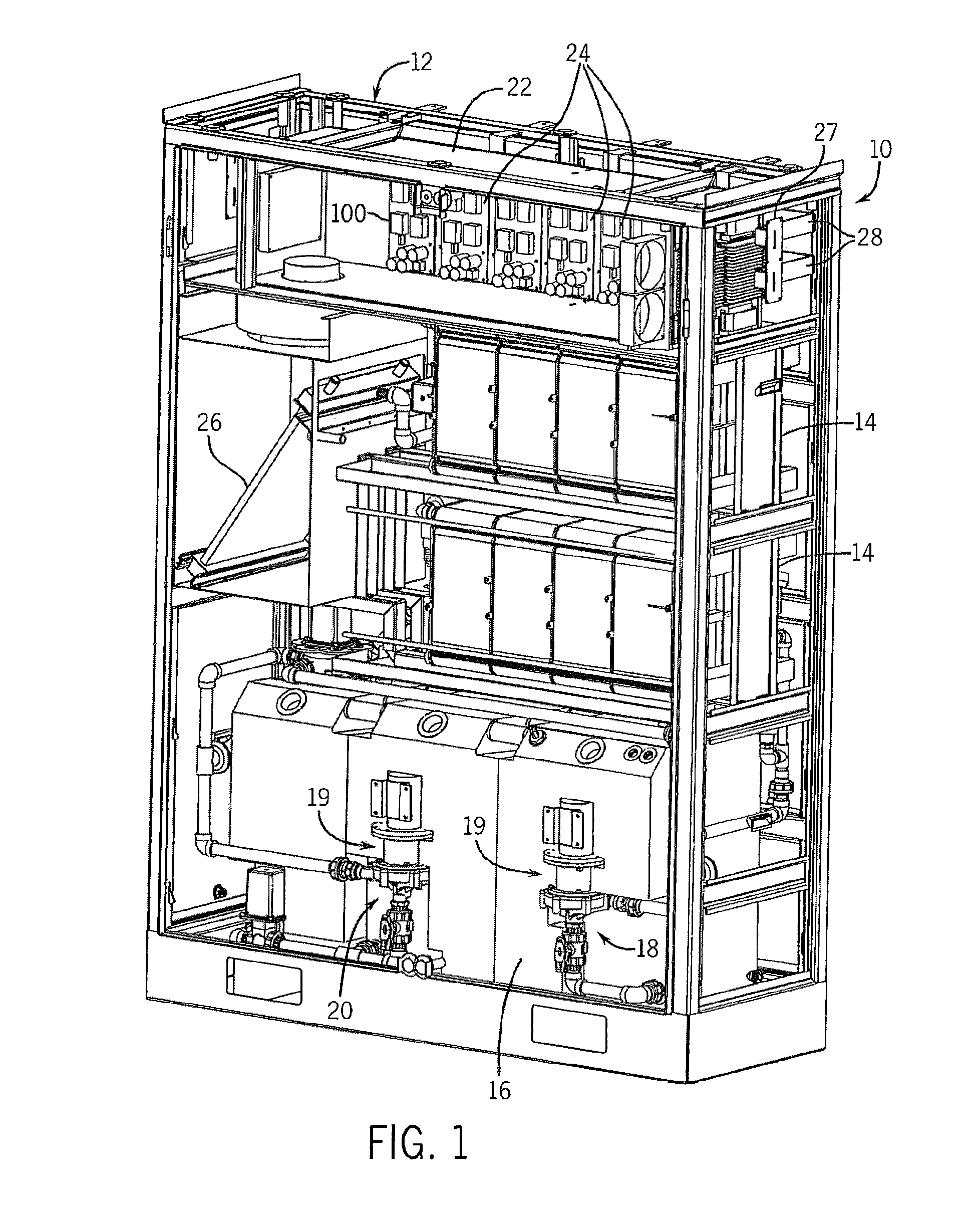
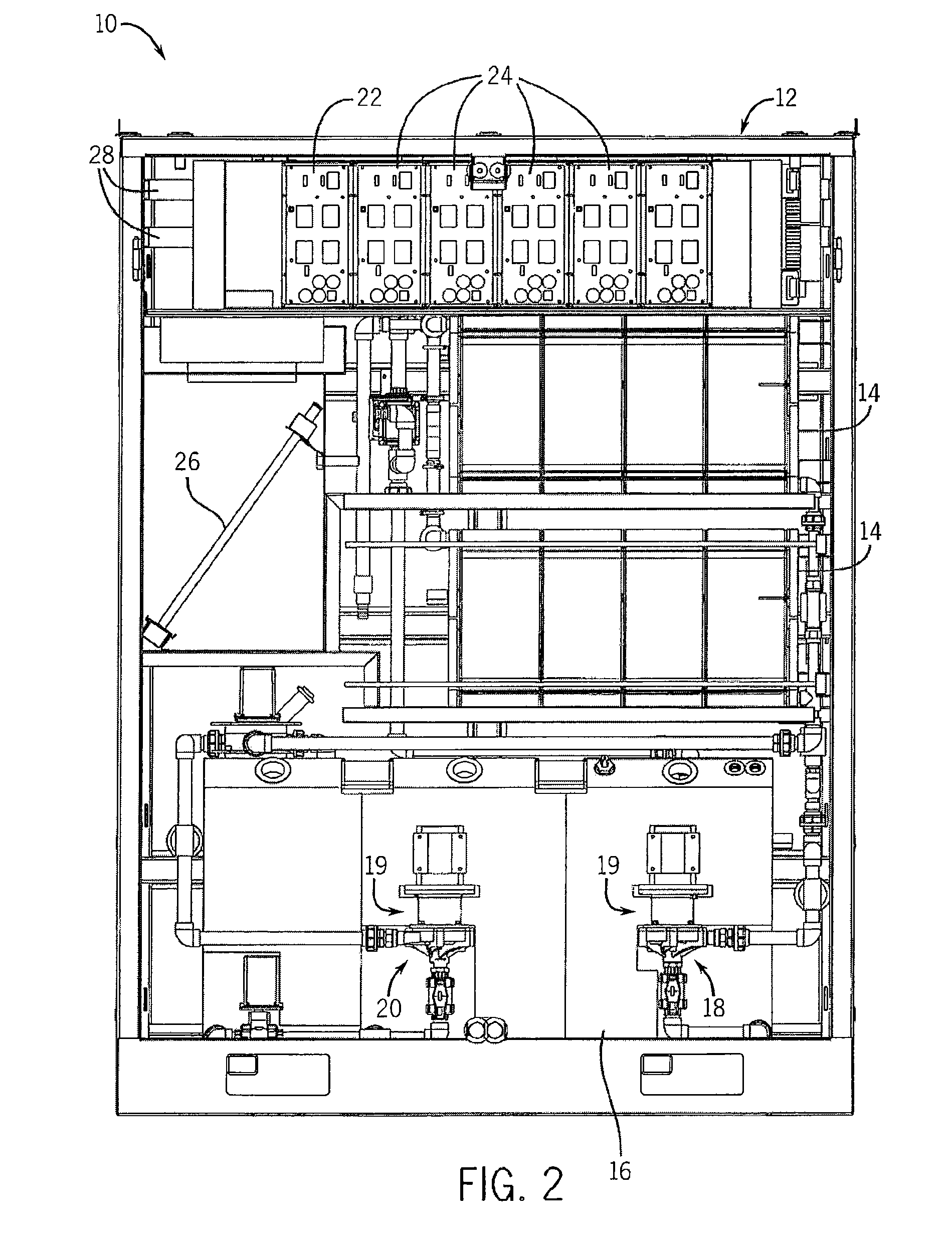
[0063]With reference now to the drawing figures in which like reference numerals designate like parts throughout the disclosure, the electrolyte battery module and system according to one embodiment of the present invention is illustrated generally at 10 in FIGS. 1-4 and 14-21. The battery system 10 includes as general components a cabinet 12, an assembly of cell stacks 14 positioned within the cabinet 12, a tank assembly 16 positioned within the cabinet 12. The tank assembly 16 includes an anolyte flow system 18 (FIGS. 5-9) and and a catholyte flow system 20 (FIGS. 10-13) each having a pump 19 and suitable piping 21 operably connected to the cell stacks 14. The anolyte is the portion of the electrolyte in proximity to the anode, or negative cell, in the battery, and, the catholyte is the portion of the electrolyte in proximity to the cathode, or positive cell, in the battery. In a discharged state, the electrolyte in each system 18, 20 is substantially identical. As the cell stacks...


PUM

PropertyMeasurementUnit
Flow rateaaaaaaaaaa
Polarityaaaaaaaaaa
Currentaaaaaaaaaa

Abstract

An improved electrolyte battery is provided that includes a tank assembly adapted to hold an amount of an anolyte and a catholyte, a number of cell stacks operably connected to the tank assembly, each stack formed of a number of flow frames disposed between end caps and a number of power converters operatively connected to the cell stacks. The cell stacks are formed with a number of flow frames each including individual inlets and outlets for anolyte and catholyte fluids and a separator disposed between flow frames defining anodic and cathodic half cells between each pair of flow frames. The power converter is configured to connect the battery with either forward or reverse polarity to a DC power source, such as a DC bus. The anodic and cathodic half cells switch as a function of the polarity by which the battery is connected to the Dc power source.

Description

CROSS-REFERENCE TO RELATED APPLICATIONS[0001]This application claims priority to U.S. provisional application Ser. No. 61 / 526,146, filed Aug. 22, 2011 and entitled Power Systems Formed with Cell Stacks Including a Number of Flowing Electrolyte Batteries and Methods of Operation. This application is also a continuation-in-part of U.S. patent application Ser. No. 13 / 185,862, filed Jul. 19, 2011 and entitled Method and Apparatus for Controlling a Hybrid Power System, which is, in turn, a continuation-in-part of U.S. patent application Ser. No. 12 / 355,169, filed Jan. 16, 2009, entitled Method and Apparatus for Controlling a Hybrid Power System, which issued as U.S. Pat. No. 8,008,808 on Aug. 30, 2011. The entire contents of each of the afore-mentioned applications are incorporated herein by reference.BACKGROUND OF THE INVENTION[0002]The present invention relates generally to power supply systems, and more specifically to power supply systems including flowing electrolyte batteries.[0003...

Claims


Application Information

Patent Timeline
IPC IPC(8): H02J7/00
CPCH02J1/10H02J7/34H02J3/382H01M8/188H01M4/8875H01M4/96H01M10/365H01M10/46H01M8/0213H01M8/0221H01M8/0226H01M12/085Y02E60/10Y02E60/50B29C45/0001B29C45/14065B29C45/1671B29D99/0096B29K2023/08B29C2045/14868B29K2223/12H01M50/1537H02J7/00H01M4/0471H01M4/668
Inventor DENNIS, KEVINCOAD, NATHANLEX, PETERREICHARD, JEFFREY A.
Owner LOTTE CHEM CORP
Why Eureka
Try Eureka