Toroidal conductivity probe with integrated circuitry

Inactive Publication Date: 2012-12-27
SGS INSTR
View PDF13 Cites 26 Cited by
  • Summary
  • Abstract
  • Description
  • Claims
  • Application Information

AI Technical Summary

Benefits of technology

[0038]In another embodiment of this invention, different winding counts, winding spacings, ferrite cores materials, toroid cross sectional sizes, or central opening sizes may be used for each of the drive and sense toroids in order to individually optimize properties of each toroid. In one exemplary implementation, relatively

Problems solved by technology

This has several disadvantages, such as electrolysis and corrosion changing the contact resistance of the electrodes, causing substantial calibration drift, and different behavior of loss mechanisms with frequency of excitation in the case of an AC signal.
It can also be challenging for extreme situations like highly corrosive or ultrahigh purity fluids.
This turns out not to be completely true.
This results in inaccurate readings or even the complete inability to measure meaningful signals for low conductivity fluids.
These shields are described as “magnetic”, however, so would not necessarily act to eliminate the capacitive coupling between drive and sense coils.
This causes additional electrical noise in the sense coil and thus in the output of the conductivity sensor if multiple shields are all joined to a common ground, as in the Reese patent.
Their device is also not well suited to measurement of a broad range of solutions and conductivities, as it relies on a specific resonance.
While this method provides very high sensitivity, it applies only to a very narrow salinity range because it is tuned for a specific resonance, so does not solve the problem of measurements over a wider range of salinities.
Such a method, however, loses the real part of the signal, whic

Method used


Image

  • Toroidal conductivity probe with integrated circuitry
  • Toroidal conductivity probe with integrated circuitry
  • Toroidal conductivity probe with integrated circuitry

Examples


Embodiment Construction

—DETAILED DESCRIPTION

[0049]The present invention and its various embodiments are described below, with reference to figures as necessary. Reference numbers are used to match particular elements described in the text with those shown in figures.

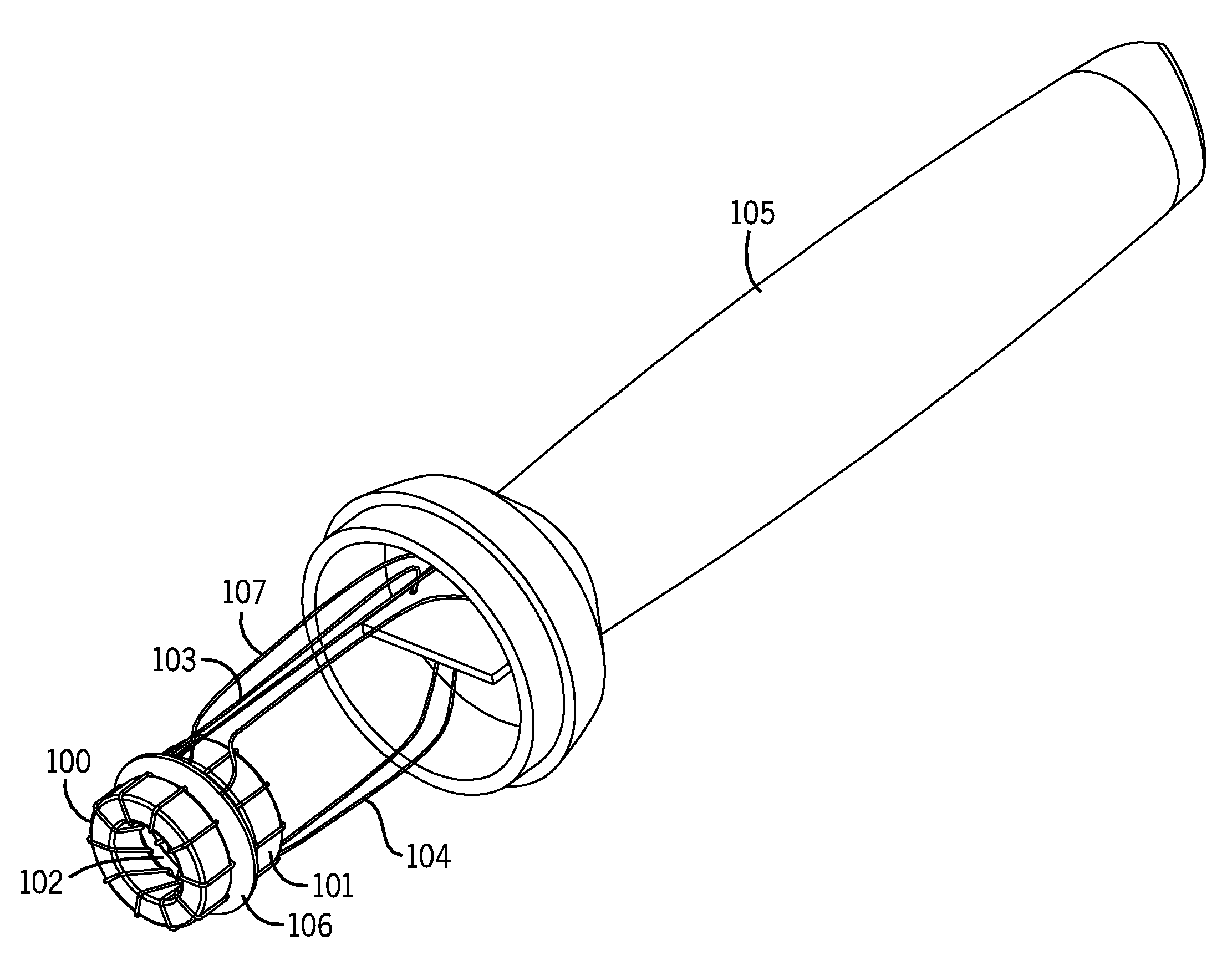
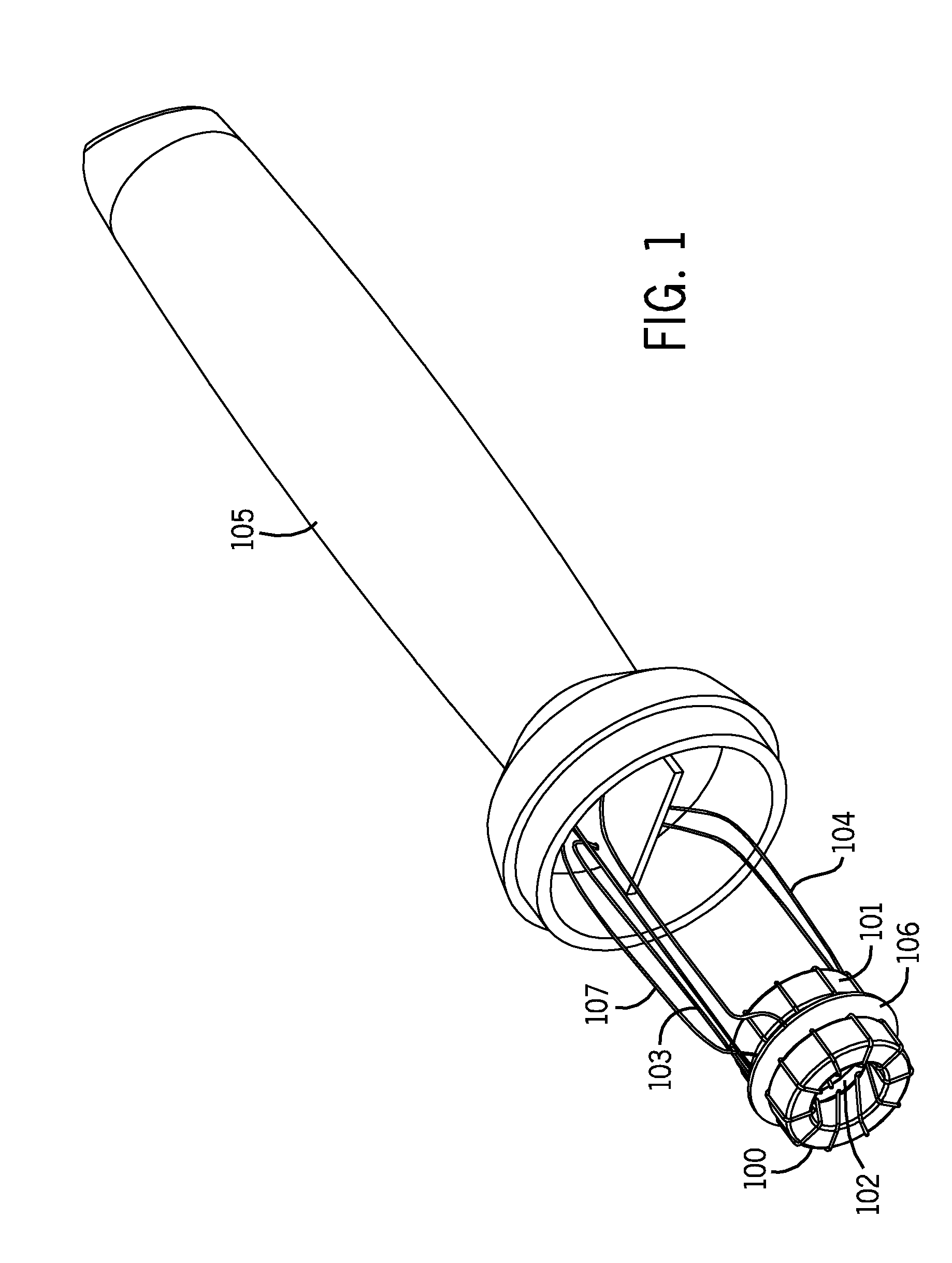
[0050]Generally speaking, the present invention describes an apparatus and associated methods of construction and operation for carrying out conductivity measurements of a fluid. FIG. 1 illustrates a conventional conductivity probe, as previously constructed. The apparatus includes at least two magnetic inductors 100 and 101, often referred to as toroids in this description though it should be appreciated that they can take other shapes, and associated magnetic circuits. These toroids are coaxially stacked around a central aperture 102 which permits fluid to flow through the aperture. This central aperture is commonly, but not exclusively, circular. AC power is supplied by means of power wires 103 to the drive or primary toroid 100 in order to...


PUM


Abstract

An apparatus and process for making noncontact measurements of liquid conductivity are disclosed. This apparatus forms a conductivity cell and uses two toroids, one to generate a magnetic field and another to sense the magnetic field, placed in an enclosure which allows liquid to pass through it for measurement. Ground planes constructed preferably of printed circuit boards with conductive layers are used to reduce capacitive coupling between the toroids and provide better shielding. Circuitry on or near these circuit boards are used to convert local, low level signals from a sensing toroid to signals which can be more readily passed to and from a recording system or operator without degradation. Sensors on or near these circuit boards can be used to sense environmental conditions in order to improve operation and stability of the conductivity cell. Methods and apparatus for increasing circuit sensitivity and calibrating the sensor are also disclosed.

Description

CROSS REFERENCE TO RELATED APPLICATIONS[0001]This application is a U.S. National Stage Utility application taking priority from PCT application PCT / US2010 / 025651 filed Feb. 26, 2010, herein incorporated by reference, which PCT application takes priority from U.S. Provisional application No. 61 / 302,122 filed Feb. 6, 2010, and also herein incorporated by reference.BACKGROUND OF INVENTIONReferences[0002]U.S. Pat. No. 2,542,057, M. J. Relis, Method and Apparatus for Measuring the Conductivity of an Electrolyte[0003]U.S. Pat. No. 3,806,798 Gross, Electrodeless Conductivity Measurement System[0004]U.S. Pat. No. 7,126,343 Howes, Conductivity Probe with Keeper[0005]U.S. Pat. No. 5,157,332, P. C. Reese, Three-Toroid Electrodeless Conductivity Cell[0006]U.S. application Ser. No. 12 / 410,443 Samad Seyfi, Apparatus and Method for Measuring Salinity of a Fluid by Inductance[0007]A. Lopes Ribeiro, “Inductive Conductivity Cell for Water Salinity Monitoring”, XVIII Imeko World Congress, Metrology fo...

Claims


Application Information

Patent Timeline
IPC IPC(8): G01R33/09G01R35/00
CPCG01N27/025G01N27/023G01N2030/645
Inventor ROPER, BRIAN KEITHROPER, TODD KENNETHLURCOTT, STEVETREPP, ROBERT
Owner SGS INSTR
Why Eureka
Try Eureka