Compression-ignition engine with exhaust system

a technology of exhaust gas treatment and compression ignition, which is applied in the direction of electrical control, process and machine control, etc., can solve the problems of increasing the nox emissions, the nox emissions are not enough to maintain the temperature of the engine the heat arriving at the scr device is no longer sufficient to maintain the temperature thereof above the required temperature threshold, etc., to prevent uncontrolled nox emissions, and reduce the nox emissions

Active Publication Date: 2013-01-03
BORGWARNER LUXEMBOURG OPERATIONS SARL +1
View PDF8 Cites 14 Cited by
  • Summary
  • Abstract
  • Description
  • Claims
  • Application Information

AI Technical Summary

Benefits of technology

[0017]The present invention thus addresses the problem that the SCR device is typically located in a position, which is relatively remote from the engine and which has the drawback that a significant quantity of heat is lost between the engine and the SCR device. Another problem of the remote position is that an important part of the exhaust line must be heated up before the SCR device finally heats up. Another problem arises from the fact that modern Diesel engines are relatively efficient and such engine produces less heat. In certain driving situations, e.g. when the motor is running idle or with low load, it may happen that the heat arriving at the SCR device is no longer sufficient to maintain the temperature thereof above the required temperature threshold. Paradoxically, the achievements in terms of fuel efficiency may thus lead to higher NOx emissions. By employing a three-way catalyst and changing over from lean mode operation (λ>1) to stoichiometric (λ=1) or rich (λ>1) combustion when the (estimated or measured) SCR device temperature drops below the required minimum temperature, the present invention prevents uncontrolled increase of NOx emissions in situations where the SCR device is too cold to have good NOx reduction capability.
[0018]Due to its close-coupled position, the three-way catalyst reaches its operating temperature quickly (even without active heat-up strategies) and also maintains a sufficient temperature in low load situations. Therefore, the three-way catalyst can provide good NOx conversion during acceleration phases occurring shortly after a cold start or after a period during which the SCR device cools down due to an extended low load operation. Good NOx conversion in the three-way catalyst is obtained by switching the engine to an operation at λ=1. The total tailpipe NOx emissions can thus be significantly reduced compared to a conventional exhaust system with an SCR device and a diesel oxidation catalyst. Even though temporary λ=1 operation may result in slightly worse (instantaneous) fuel efficiency, the overall CO2 emissions (over an entire test cycle) are lower than in conventional systems wherein heat-up strategies are applied to have a faster warm-up of the SCR system or to keep the SCR device at its optimum temperature.

Problems solved by technology

Another problem of the remote position is that an important part of the exhaust line must be heated up before the SCR device finally heats up.
Another problem arises from the fact that modern Diesel engines are relatively efficient and such engine produces less heat.
In certain driving situations, e.g. when the motor is running idle or with low load, it may happen that the heat arriving at the SCR device is no longer sufficient to maintain the temperature thereof above the required temperature threshold.
Paradoxically, the achievements in terms of fuel efficiency may thus lead to higher NOx emissions.
Even though temporary λ=1 operation may result in slightly worse (instantaneous) fuel efficiency, the overall CO2 emissions (over an entire test cycle) are lower than in conventional systems wherein heat-up strategies are applied to have a faster warm-up of the SCR system or to keep the SCR device at its optimum temperature.

Method used


Image

  • Compression-ignition engine with exhaust system
  • Compression-ignition engine with exhaust system
  • Compression-ignition engine with exhaust system

Examples


Embodiment Construction

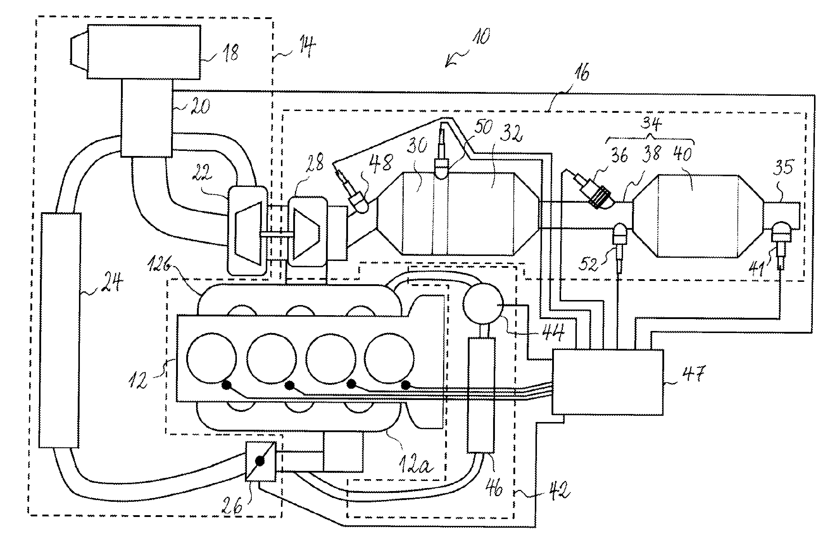
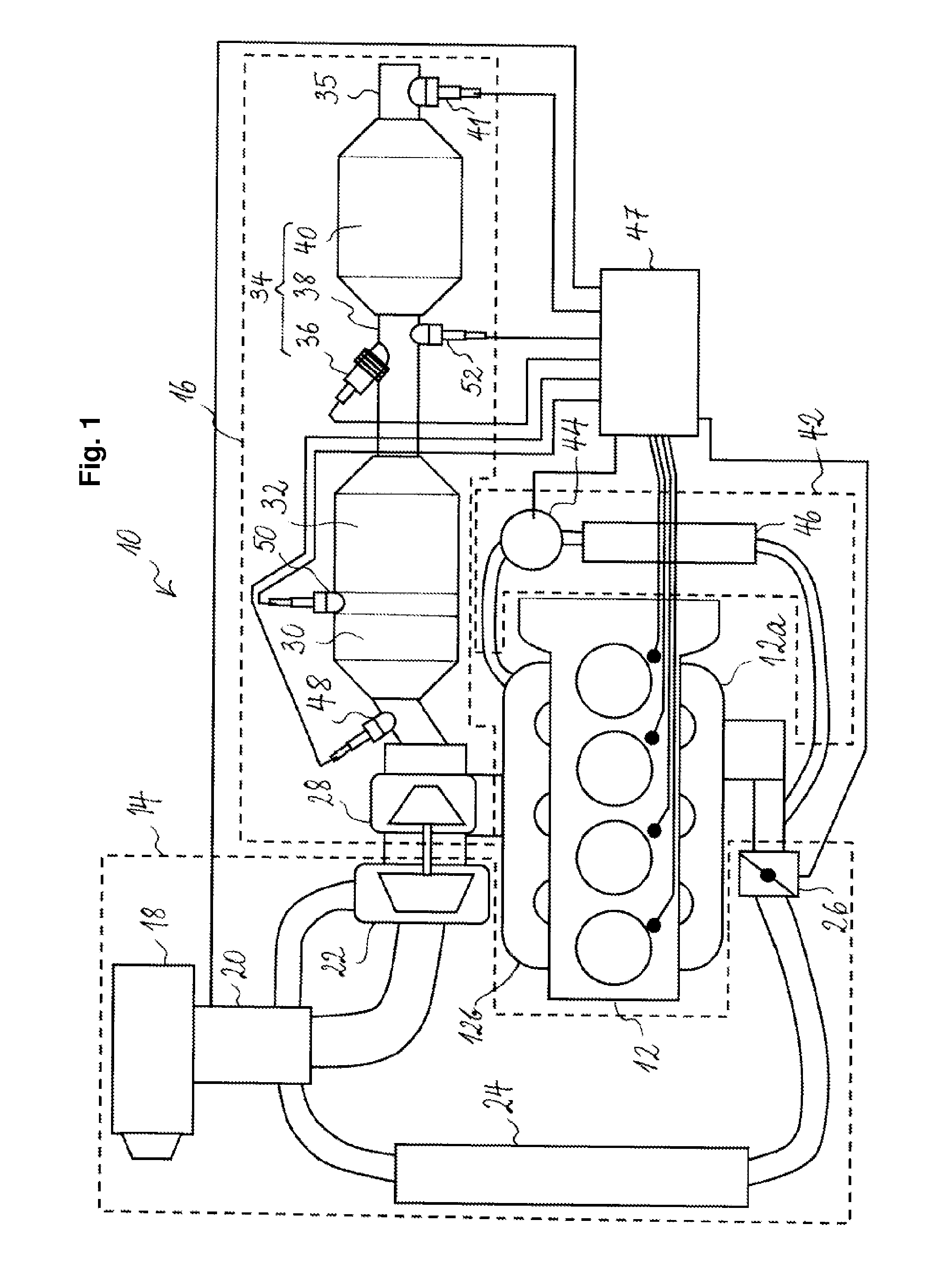
[0032]Referring to FIG. 1, a diesel compression-ignition engine 10 according to a preferred embodiment of the present invention is shown. The engine 10 comprises an engine block 12 connected up-stream to an air intake passage 14 and down-stream to an exhaust system 16 with an exhaust gas after-treatment assembly.

[0033]The air intake passage 14 comprises an air filter 18 to filter air draw from the outside into the engine, a mass air flow sensor 20, a turbocharger 22 an intercooler 24 and a throttle valve 26 connected upstream to intake manifold 12a.

[0034]Exhaust system 16 comprises the turbine 28 of turbocharger 22, connected downstream to the exhaust manifold 12b of the engine, a three-way catalyst device 30, a diesel particulate filter 32 and an SCR device 34 arranged upstream of tailpipe 35. SCR device 34 includes a urea or ammonia injector 36, a decomposition (in case of urea injection) and / or mixing chamber 38, an SCR catalyst 40 connected downstream to the decomposition and / o...


PUM


Abstract

A compression-ignition engine (10) comprises an exhaust system (16) with an exhaust gas after-treatment assembly, the after-treatment assembly comprising a three-way catalyst device (30) and an SCR device (34), the three-way catalyst device being arranged upstream the SCR device in close-coupled position with respect to the engine. An engine control unit (47) is provided for controlling operation of the engine. The engine control unit is configured to monitor the temperature of the SCR device and to control the engine to change over from an operation with a lean air/fuel mixture to an operation with a stoichiometric or a rich air/fuel mixture in response to the temperature of the SCR device dropping below a temperature threshold.

Description

TECHNICAL FIELD[0001]The present invention relates generally to exhaust gas treatment for compression ignition engine for vehicles.BACKGROUND ART[0002]Due to chemical reactions and the incomplete combustion of fuel in the combustion chamber of an internal combustion engine, the gases emitted from the exhaust system of the engine may contain a number of hazardous substances, which can lead to air pollution problems that may be detrimental to health and the environment. The main pollutants of concern in the gases emitted from the exhaust system of an internal combustion engine are hydrocarbons (HC), carbon monoxide (CO), oxides of nitrogen (NOx), and particulates (i.e. soot).[0003]An ever-increasing number of vehicles has resulted in increasing air pollution, particularly in urban areas. Therefore, a series of ever-stricter emission standards have been imposed to mitigate these pollution problems.[0004]In order to reduce the emissions of HC, CO, and NOx from gasoline-fuelled spark ign...

Claims


Application Information

Patent Timeline
Patent Type & Authority Applications(United States)
IPC IPC(8): F01N3/10F02D41/26
CPCF01N3/021F01N3/035F01N3/101F01N3/2066F01N3/2882F01N13/009F02B29/0406F02M25/0707F02M25/0727Y02T10/22Y02T10/24F01N2610/02F02M26/05F02M26/23Y02T10/12
Inventor SCHREURS, BART HUBERT
Owner BORGWARNER LUXEMBOURG OPERATIONS SARL
Why Eureka
Try Eureka