Liquid Separation by membrane assisted vapor stripping process

a technology of vapor stripping and liquid separation, which is applied in the direction of membranes, vacuum distillation separation, separation processes, etc., can solve the problems of reducing stripping and overall separation efficiency, reducing standard distillation, and unable to reach standard distillation

Inactive Publication Date: 2013-01-17
ENVIRONMENTAL PROTECTION AGENCY US
View PDF14 Cites 24 Cited by
  • Summary
  • Abstract
  • Description
  • Claims
  • Application Information

AI Technical Summary

Problems solved by technology

Further, standard distillation is only able to reach the ethanol-water azeotrope —about 5 wt % water.
Such a process would also be useful for recovering ethanol from dilute process or waste streams not currently attractive due to the inefficiency of distillation, particularly in smaller installations in which the economies of scale do not favor distillation.
Unfortunately, the inert gas dilutes the volatile product, making recovery of the product by condensation more energy intensive.
However, in situations where the components are fully miscible and the VLE behavior is not highly favorable, stripping and overall separation efficiencies decrease.
In addition, lower alcohols are fully miscible with water in the overhead condensate.
Although it acts to improve the separation performance of most distillation columns, return of reflux condensate to the column increases the heat required in the reboiler.
However, below 3 wt %, the energy of distillation rises rapidly and will exceed the heat of combustion when the feed concentration drops below 1 wt %.
For this reason, the recovery of ethanol from streams containing less than 3 wt % is not very attractive from an energy standpoint.
However, heat integration of this kind is more complicated to design / operate and requires additional equipment, thus increasing the capital cost.
Such complexity is acceptable for larger scale operations, but becomes less so when the operation is scaled down and the relative cost increases.
However, the invention of Baker does not produce dry solvent.
It does not teach separation of water-organic solvent mixtures.
Matson '571 teaches that the gas-free permeate vapor is much more economically compressed from an energy standpoint than is the overhead from stripping column stating that “this method [compressing the entire overhead mixture] is impractical because of the large energy requirement associated with compressing the stripped gas present with the vapor”.

Method used


Image

  • Liquid Separation by membrane assisted vapor stripping process
  • Liquid Separation by membrane assisted vapor stripping process
  • Liquid Separation by membrane assisted vapor stripping process

Examples


example 1

Effect of Non-Condensable Gas on Vapor Stripper, Compressor, and Membrane Systems

[0086]As noted previously, the use of non-condensable gases to strip organic compounds from water followed by the recovery and reuse of the gas has been taught in prior art. In order to test whether the absence of non-condensable gases is advantageous according to the present invention, the efficiency and cost of the compressor and membrane systems required in the process for a hypothetical overhead vapor as a function of non-condensable gas content were estimated. The ethanol-water binary mixture was chosen as the model system. The chemical process simulation program ChemCAD 5.4 (ChemStations, Houston, Tex., USA) was used to perform steady state calculations. ChemCAD was also used for most equipment sizing and costing. Exceptions were liquid pumps, liquid storage tanks and distillation / stripping towers, for which literature sizing / costing relationships were used. Column height was based on an assumptio...

example 2

Production of Fuel-Grade Ethanol from Dilute Fermentation Broths

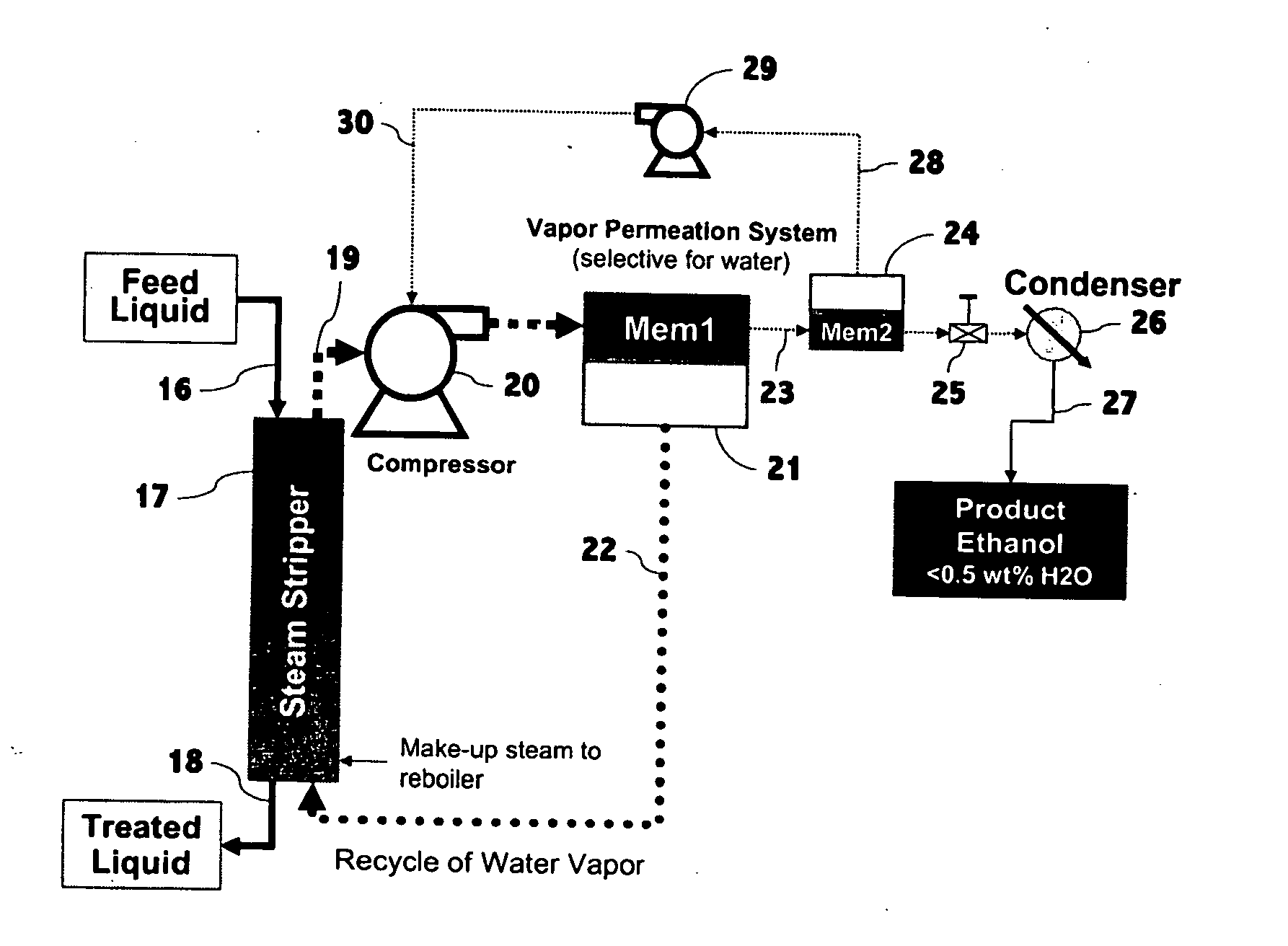
[0097]The energy usage and capital / operating costs according to the present invention were estimated for the recovery of ethanol from aqueous fermentation broths containing 1 or 5 wt % ethanol. The schematic diagram of the standard configuration of the present invention considered in this example is shown in FIG. 5, which is a schematic diagram of a process according to the present invention in which permeate from the first membrane stage is returned as vapor to act as stripping vapor in the stripping column. Permeate from second stage membrane is directed to the suction side of the overhead compressor. Retentate vapor is optionally condensed by heat exchange with the reboiler.

[0098]Referring with particularity to the drawings, in FIG. 5 there is the feed liquid stream, 43, which feeds into the stripping column, 44. A stream of bottoms liquid or treated liquid, 45, exits the bottom of the stripping column. Said bottoms ...

example 3

Effect of Stripper Pressure and Compressor Discharge Pressure on Energy Usage

[0124]In example 2, the calculated energy benefits of the present invention relative to that of distillation were presented for the separation of ethanol / water mixtures. In that example, the operating temperature of the stripping column for the present invention was fixed at 55° C. In this example, the effect of stripper temperature (which determines the stripper pressure) and of the overhead compressor discharge pressure (which is the same as membrane feed pressure in the present invention) on energy usage for the present invention are calculated for ethanol-water mixtures of 1 and 5 wt % ethanol. The general basis assumptions are the same as those in Example 2 and generic schematic diagrams for the 2- and 3-membrane systems for this example are the same as those in Example 2 and are presented in FIGS. 5 and 11.

[0125]Raising stripper operating temperature also raises the operating pressure of the stripper,...


PUM

PropertyMeasurementUnit
energyaaaaaaaaaa
energyaaaaaaaaaa
permeableaaaaaaaaaa

Abstract

An improved process for separation of liquid mixtures involves vapor stripping followed by mechanical compression of the vapor which is then exposed to a permeation membrane for separation of the compressed vapor. The apparatus for separating a liquid mixture of two or more solvents comprises components a stripping column, at least one over-head compressor and, thereafter, at least one selectively permeable membrane wherein the membrane separates the components of the vapor based on the different sorption and diffusion characteristics.

Description

[0001]This application is a continuation of U.S. application Ser. No. 11 / 896,201 filed Aug. 30, 2007, now pending.FIELD AND BACKGROUND OF THE INVENTION[0002]This invention relates to the field of separation of liquids using stripping means. The process of the invention involves vapor stripping followed by mechanical compression of the vapor which is then exposed to a permeation membrane for separation of the compressed vapor.[0003]Distillation is the most common separation unit operation for miscible liquid mixtures in the chemical industry, including facilities producing ethanol. Although distillation has proven to be a robust and efficient method for removing and concentrating ethanol (EtOH) from fermentation broths, the energy efficiency of distillation declines dramatically below an ethanol concentration of 5 wt %. Processes proposed for the conversion of lignocellulosic biomass and waste materials to ethanol may deliver ethanol concentrations less than 5 wt %. As a result, proc...

Claims


Application Information

Patent Timeline
Patent Type & Authority Applications(United States)
IPC IPC(8): B01D61/36
CPCB01D1/28B01D3/002B01D3/145B01D3/38B01D61/36B01D2311/04C07C45/786C07C29/76C07C29/80B01D2311/26C07C31/04C07C31/08C07C31/12B01D61/363
Inventor VANE, LELAND M.ALVAREZ, FRANKLIN R.
Owner ENVIRONMENTAL PROTECTION AGENCY US
Why Eureka
Try Eureka