

Power storage device, electrode, and manufacturing method thereof
a technology of power storage and electrodes, applied in the manufacturing process of electrodes, cell components, coatings, etc., can solve the problems of reducing the conductivity of lithium ion between an electrode and an electrolyte, reducing the coulombic efficiency, and reducing the lithium ion conductivity. , to achieve the effect of inhibiting the separation of the carbon layer
- Summary
- Abstract
- Description
- Claims
- Application Information
AI Technical Summary
Benefits of technology
Problems solved by technology
Method used
Image

Examples
embodiment 1
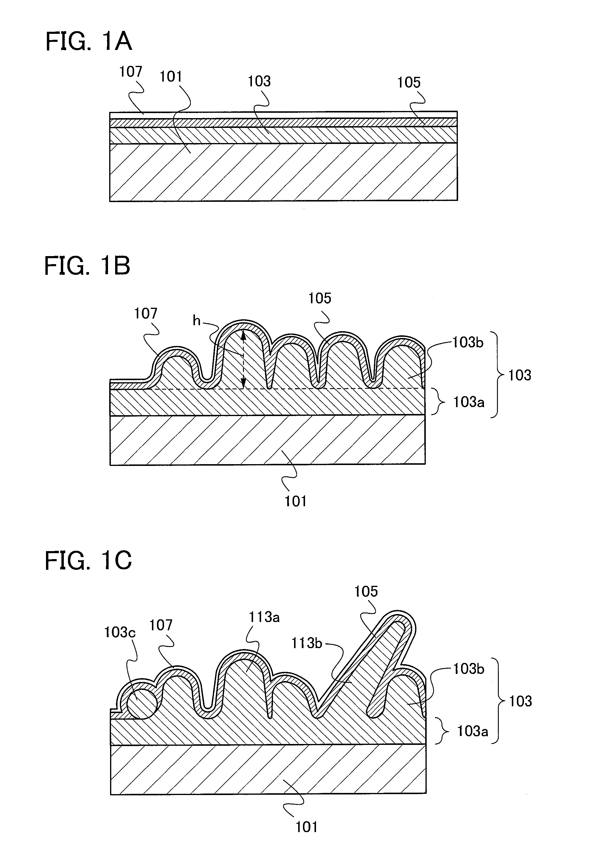
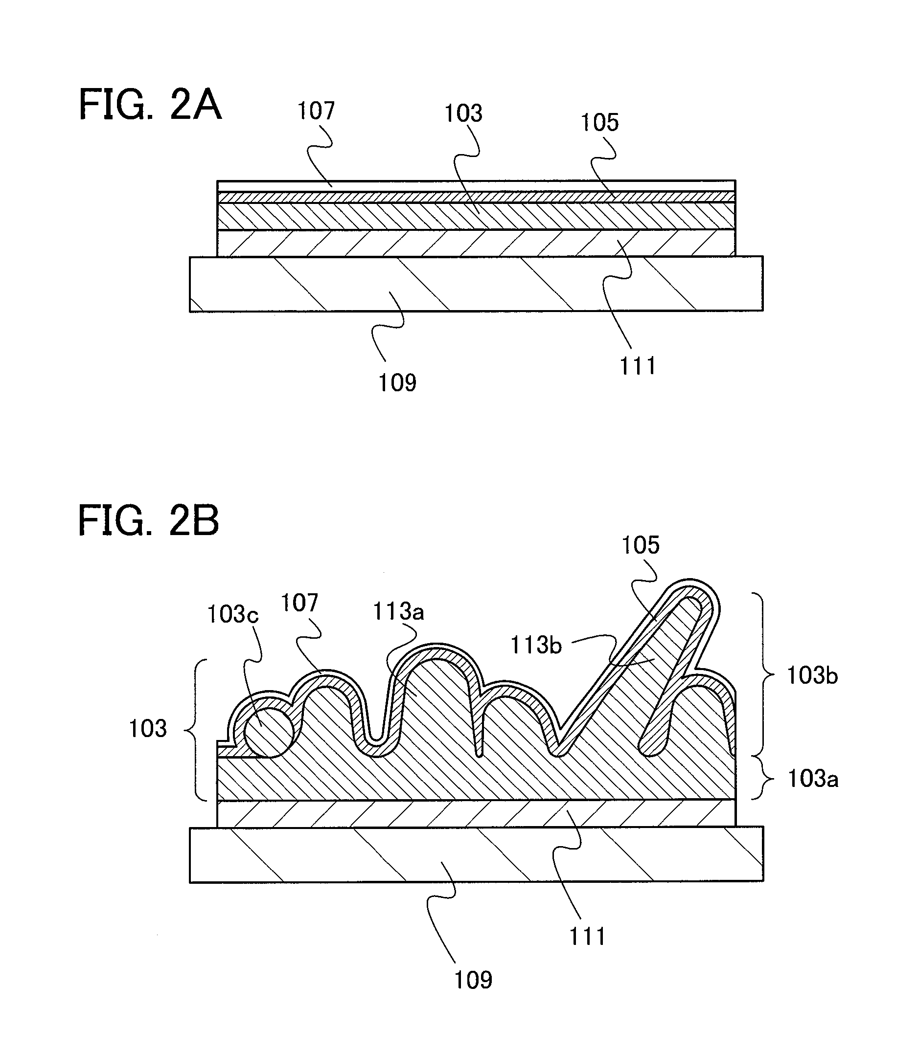
[0032]In this embodiment, an electrode of a power storage device according to one embodiment of the present invention and a method for manufacturing the electrode will be described with reference to FIGS. 1A to 1C and FIGS. 2A and 2B.
[0033]First, a silicon layer is formed as an active material layer 103 over a current collector 101 by an evaporation method, a sputtering method, a plasma CVD method, a thermal CVD method (preferably a low-pressure chemical vapor deposition (LPCVD) method), or the like (see FIG. 1A).
[0034]The current collector 101 functions as a current collector of the electrode. Thus, a conductive material having a foil shape, a plate shape, or a net shape is used. For example, the current collector 101 can be formed using a metal element with high conductivity, typified by platinum, aluminum, copper, or titanium. Alternatively, an aluminum alloy to which silicon, titanium, neodymium, scandium, molybdenum, or the like is added in order to improve heat resistance may ...
embodiment 2
[0065]In this embodiment, a structure of a power storage device will be described with reference to FIGS. 3A and 3B.
[0066]First, a structure of a secondary battery which is an example of a power storage device will be described. Among secondary batteries, a lithium-ion secondary battery formed using a lithium-containing metal oxide such as lithium iron phosphate or lithium cobalt oxide, or the like has high discharge capacity. Here, a structure of a lithium-ion secondary battery, a typical example of a secondary battery, will be described.
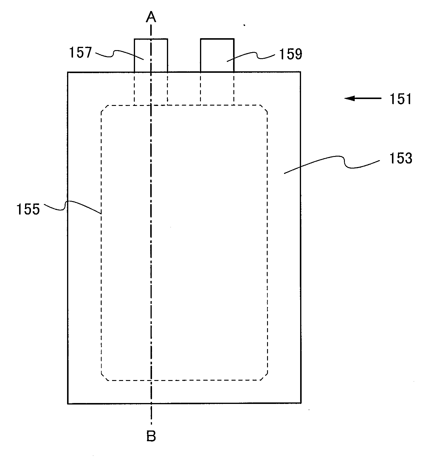
[0067]FIG. 3A is a plan view of a power storage device 151, and FIG. 3B is a cross-sectional view along dashed dotted line A-B in FIG. 3A.
[0068]The power storage device 151 in FIG. 3A includes a power storage cell 155 in an exterior member 153. The power storage device 151 further includes terminal portions 157 and 159 which are connected to the power storage cell 155. For the exterior member 153, a laminate film, a polymer film, a metal film, a me...
embodiment 3
[0088]The power storage device according to one embodiment of the present invention can be used for power supplies of a variety of electronic devices and electric appliances which can be operated with power.
[0089]Specific examples of electronic devices and electric appliances each utilizing the power storage device according to one embodiment of the present invention are as follows: display devices, lighting devices, desktop personal computers and laptop personal computers, image reproduction devices which reproduce still images and moving images stored in recording media such as digital versatile discs (DVDs), mobile phones, portable game machines, portable information terminals, e-book readers, video cameras, digital still cameras, high-frequency heating appliances such as microwave ovens, electric rice cookers, electric washing machines, air-conditioning systems such as air conditioners, electric appliances such as electric refrigerators, electric freezers, and electric refrigera...
PUM
| Property | Measurement | Unit |
|---|---|---|
| Thickness | aaaaa | aaaaa |
| Thickness | aaaaa | aaaaa |
| Thickness | aaaaa | aaaaa |
Abstract
Description
Claims
Application Information