Process for production of honeycomb structure, honeycomb structure, and particulate filter

a technology of honeycomb and manufacturing method, which is applied in the field of honeycomb structure manufacturing method, honeycomb structure, and particulate filter, can solve the problems of increasing pressure loss, difficult to obtain a honeycomb structure having a desired fine particle collection function and a desired pressure loss, and increasing pressure loss, so as to prevent an increase in pressure loss, prevent the leakage of the object, and maintain the collecting efficiency of the object

Inactive Publication Date: 2013-03-14
SUMITOMO CHEM CO LTD
View PDF1 Cites 17 Cited by
  • Summary
  • Abstract
  • Description
  • Claims
  • Application Information

AI Technical Summary

Benefits of technology

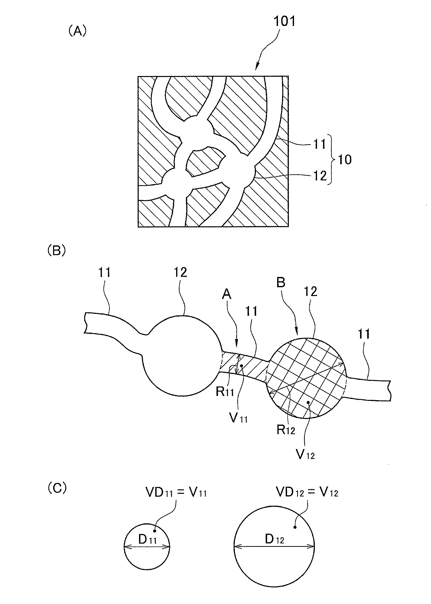
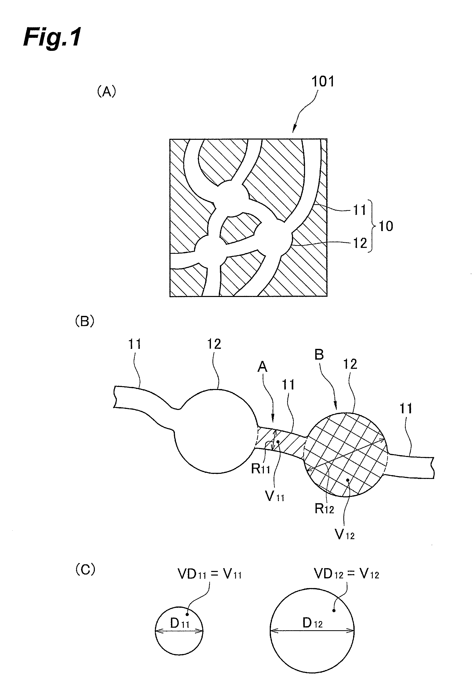
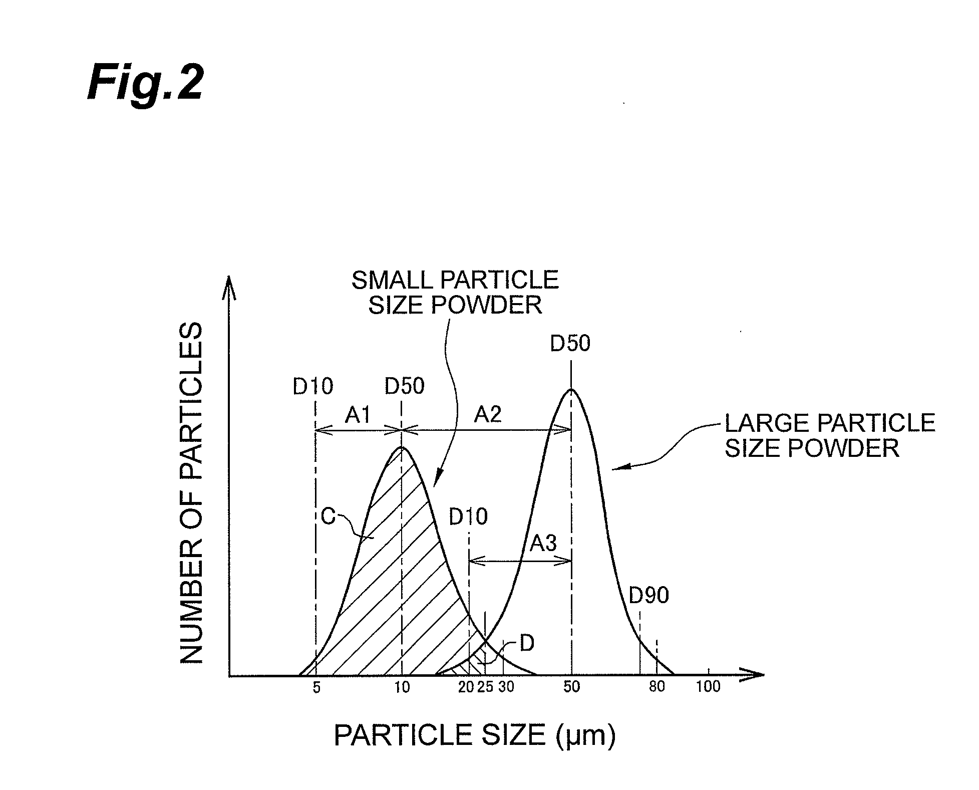
[0037]In the first invention, the pore-forming agent disappears when sintering the molded article, and hence a pore is formed at a position where the pore-forming agent disappears. In the first invention, since the pore-forming agent is obtained by mixing the small particle size powder and the large particle size powder, a pore group in which the large size pores are connected to each other through the small size pore can be formed in the partition wall of the honeycomb structure. Further, since the median particle size of the small particle size powder is 5 to 20 μm, the small size pore can be maintained at a certain size, accordingly, it is possible to prevent an increase in the pressure loss while highly maintaining the collecting efficiency of an object to be collected such as fine particles. Further, since the median particle size of the large particle size powder is 30 μm or more and the ninety-percentage particle size of the large particle size powder is 80 μm or less, it is possible to prevent the leakage of the object to be collected while suppressing the pressure loss to be low. As a result, according to the first invention, it is possible to improve the collecting efficiency of the object to be collected, and to reduce the pressure loss.
[0038]According to the second invention, since it is possible to appropriately adjust the ratio of the small size pore connecting the large size pores to each other, it is possible to further prevent the leakage of the object to be collected while further suppressing the pressure loss to be low.
[0039]According to the third invention, since it is possible to adjust the porosity in the partition wall to be an appropriate value, it is possible to appropriately adjust the ratio of the small size pore connecting the large size pores to each other. Accordingly, it is possible to further prevent the leakage of the object to be collected while further suppressing the pressure loss to be low.
[0040]According to the fourth invention, since a difference between the pore size of the large size pore and the pore size of the small size pore can be maintained to be large to some extent, it is possible to further highly maintain the collecting efficiency of the object to be collected in the large size pore.
[0041]According to the fifth invention, since a difference between the pore size of the large size pore and the pore size of the small size pore can be maintained to be large to some extent, it is possible to further highly maintain the collecting efficiency of the object to be collected in the large size pore. In addition, the pore size of the large size pore and the pore size of the small size pore formed in the partition wall can be respectively made uniform to some extent. Accordingly, it is possible to uniformly form the pores throughout the entire surface of the partition wall.
[0042]According to the sixth invention, since the amount of the small size powder contained in the large particle size powder is small, it is possible to maintain the ratio of the large size pore and the ratio of the small size pore in a certain range. Accordingly, since it is possible to prevent the narrow flow channel composed of the small size pore from being excessively formed, it is possible to further suppress an increase in the pressure loss of the honeycomb structure and suppress the local deposition of the object to be collected.

Problems solved by technology

That is, the pressure loss as the particulate filter increases.
However, in the technique of Patent Literature 2, the state of the pore inside the partition wall is not controlled, and hence it is difficult to obtain a honeycomb structure having a desired fine particle collecting function and a desired pressure loss.
However, when the pore size of the small size pore increases, the fine particle collecting function is not sufficiently exhibited, in contrast, when the pore size of the small size pore decreases, the pressure loss increases.
Then, in the technique of Patent Literature 3, since the small size pore connecting the large size pores to each other is a pore naturally formed in a matrix, it is difficult to control the pore size of the small size pore.
Accordingly, even in the technique of Patent Literature 3, it is difficult to control the state of the small size pore inside the partition wall, for this reason, it is difficult to obtain a carbide porous body having a desired fine particle collecting function and a desired pressure loss.
That is, in any of the techniques of Patent Literatures 2 and 3, it is difficult to control the state of the pore in the partition wall, and hence it is difficult to obtain a honeycomb structure or a carbide porous body capable of improving the collecting efficiency of an object to be collected such as fine particles and reducing the pressure loss.

Method used


Image

  • Process for production of honeycomb structure, honeycomb structure, and particulate filter
  • Process for production of honeycomb structure, honeycomb structure, and particulate filter
  • Process for production of honeycomb structure, honeycomb structure, and particulate filter

Examples


example 1

[0251]In Example 1, the following raw material powder was used. As the composition of the following raw material powder, the mole ratio in terms of alumina [Al2O3], titania [TiO2], magnesia [MgO] and silica [SiO2] was [Al2O3] / [TiO2] / [MgO] / [SiO2]=35.1% / 51.3% / 9.6% / 4.0%.

[0252]Further, the content percentage of the silicon source powder in the total amount of the aluminum source powder, the titanium source powder, the magnesium source powder and the silicon source powder was 4.0 mass %.

(Raw Material Powder)

(1) Aluminum Source Powder

[0253]Aluminum oxide powder (α-alumina powder) with median particle size (D50) of 29 μm

[0254]38.48 parts by mass

(2) Titanium Source Powder

[0255]Titanium oxide powder (rutile type crystal) with D50 of 1.0 μm

[0256]41.18 parts by mass

(3) Magnesium Source Powder

[0257]Magnesium oxide powder with D50 of 3.4 μm

[0258]2.75 parts by mass

(4) Silicon Source Powder

[0259]Glass frit (deformation point: 642° C.) with D50 of 8.5 μm

[0260]3.29 parts by mass

(5) Pore-Forming Agen...

example 2

[0277]In Example 2, a honeycomb-like porous sintered body was obtained as in Example 1 except that the mixture ratio of the pore-forming agent was changed, the mixture amount of the respective raw material powders was changed, and the aluminum magnesium titanate powder was added.

[0278]As the composition of the respective raw material powders, the mole ratio in terms of alumina [Al2O3], titania [TiO2], magnesia [MgO] and silica [SiO2] was [Al2O3] / [TiO2] / [MgO] / [SiO2]=35.1% / 51.3% / 9.6% / 4.0%.

[0279]Further, the content percentage of the silicon source powder in the total amount of the aluminum source powder, the titanium source powder, the magnesium source powder, the aluminum magnesium titanate powder and the silicon source powder was 4.0 mass %.

(Raw Material Powder)

(1) Aluminum Source Powder

[0280]Aluminum oxide powder (α-alumina powder) with median particle size (D50) of 29 μm

[0281]35.59 parts by mass

(2) Titanium Source Powder

[0282]Titanium oxide powder (rutile type crystal) with D50 of...


PUM

PropertyMeasurementUnit
particle sizeaaaaaaaaaa

Abstract

A method of manufacturing a honeycomb structure comprises a step of forming a molded article by molding a raw material containing a ceramic powder and a pore-forming agent; and a step of manufacturing a honeycomb structure by sintering the molded article, wherein the pore-forming agent is powder formed of a material that disappears at a sintering temperature or less where the molded article is sintered, the powder is obtained by mixing a small particle size powder and a large particle size powder, a median particle size of which a ratio of a cumulative mass with respect to a total mass of the small particle size powder is 50% is 5 to 20 μm, a median particle size of which a ratio of a cumulative mass with respect to a total mass of the large particle size powder is 50% is 30 μm or more, and a ninety-percentage particle size of which a ratio of a cumulative mass with respect to a total mass of the large particle size powder is 90% is 80 μm or less.

Description

TECHNICAL FIELD[0001]The present invention relates to a honeycomb structure manufacturing method, a honeycomb structure, and a particulate filter. Specifically, the invention relates to a particulate filter which achieves purification of an exhaust gas by collecting fine particles such as soot in the exhaust gas discharged from an internal-combustion engine such as a diesel engine or a gasoline engine, a honeycomb structure which is appropriately used as a ceramic filter like the particulate filter, and a manufacturing method thereof.BACKGROUND ART[0002]As a ceramic filter which removes an object to be collected from a fluid containing the object to be collected, there are known an exhaust gas filter which purifies an exhaust gas discharged from an internal-combustion engine; a filtration filter used for filtration of food, drink and the like; a selective permeation filter through which a gas component selectively permeates; and the like. For example, currently, in a diesel engine a...

Claims


Application Information

Patent Timeline
Patent Type & Authority Applications(United States)
IPC IPC(8): B29C67/20B01D24/00B01D39/14
CPCB01D39/2093B01D46/2474B01J35/04C04B35/478C04B38/0006C04B2111/00793C04B2111/0081C04B2235/3206C04B2235/3418C04B2235/36C04B2235/5436C04B2235/658C04B2235/6584F01N3/0222B01D2239/10B01D46/2429B01D46/0001C04B2235/80B01D24/001B01D39/14B29C67/202C04B35/638C04B38/0009C04B2235/3218C04B2235/3222C04B2235/3234C04B2235/3427C04B2235/3463C04B2235/3826C04B2235/3852C04B2235/3873C04B2235/3886C04B2235/401C04B2235/402C04B2235/441C04B2235/446C04B2235/449C04B2235/5472C04B2235/652C04B38/0054C04B38/0074B01D46/2482B01D46/24491B01D46/24492
Inventor KOBASHI, YASUHARUTOHMA, TETSUROIWASAKI, KENTARO
Owner SUMITOMO CHEM CO LTD
Why Eureka
Try Eureka