

Lithium air battery
- Summary
- Abstract
- Description
- Claims
- Application Information
AI Technical Summary
Benefits of technology
Problems solved by technology
Method used
Image

Examples
example 1
[0065]28 mmol of resorcinol (Aldrich-Sigma Co. Ltd.) was mixed with 120 mmol of formaldehyde (a 37% aqueous solution, Aldrich-Sigma Co. Ltd.), and sodium carbonate and resorcinol were added to the solution in a mole ratio of 45:100. The resulting solution was mixed at 75° C. for 1 hour to obtain a gel mixture. The gel mixture was aged at room temperature for 24 hours. The aged mixture was washed with water and ethanol to remove the sodium carbonate therein. The obtained structure was dipped in a tributylphenyltin (Aldrich-Sigma Co. Ltd.) solution for a day and heat-treated at 700° C. for 2 hours under an Ar atmosphere, preparing a Sn—C composite.
[0066]The Sn—C composite powder was mixed with polyvinylidene fluoride (PVdF) and carbon black (super P) in a weight ratio of 80:10:10, and the mixture was dispersed into N-methyl-2-pyrrolidone, preparing a negative active material layer composition. The negative active material layer composition was coated on a copper foil. The resulting pr...
example 2
[0069]Si powder having a size of 100 nm and natural graphite powder having a size of 5 μm were mixed in a weight ratio of 30:70, and the mixture was added to a tetrahydrofuran solution. Next, 33 parts by weight of pitch was added to 100 parts by weight of the mixed solution. The mixture was ball-milled for 12 hours. The mixed solution was dried in a 100° C. vacuum oven for 6 hours and heat-treated at 1000° C. for 5 hours under an Ar atmosphere, fabricating a Si—C composite.
[0070]The Si—C composite powder was mixed with carbon black (super P), carboxylmethyl cellulose, and styrene-butadiene rubber in a weight ratio of 85:5:3.3:6.7 in water, preparing a negative active material layer composition. The negative active material layer composition was casted on a copper foil, and the casted foil was dried in a 100° C. oven for 2 hours and vacuum-dried for greater than or equal to 12 hours, fabricating a negative electrode.
[0071]On the other hand, a positive active material layer compositio...
experimental example 1
Electrochemical Performance of Lithium Air Battery
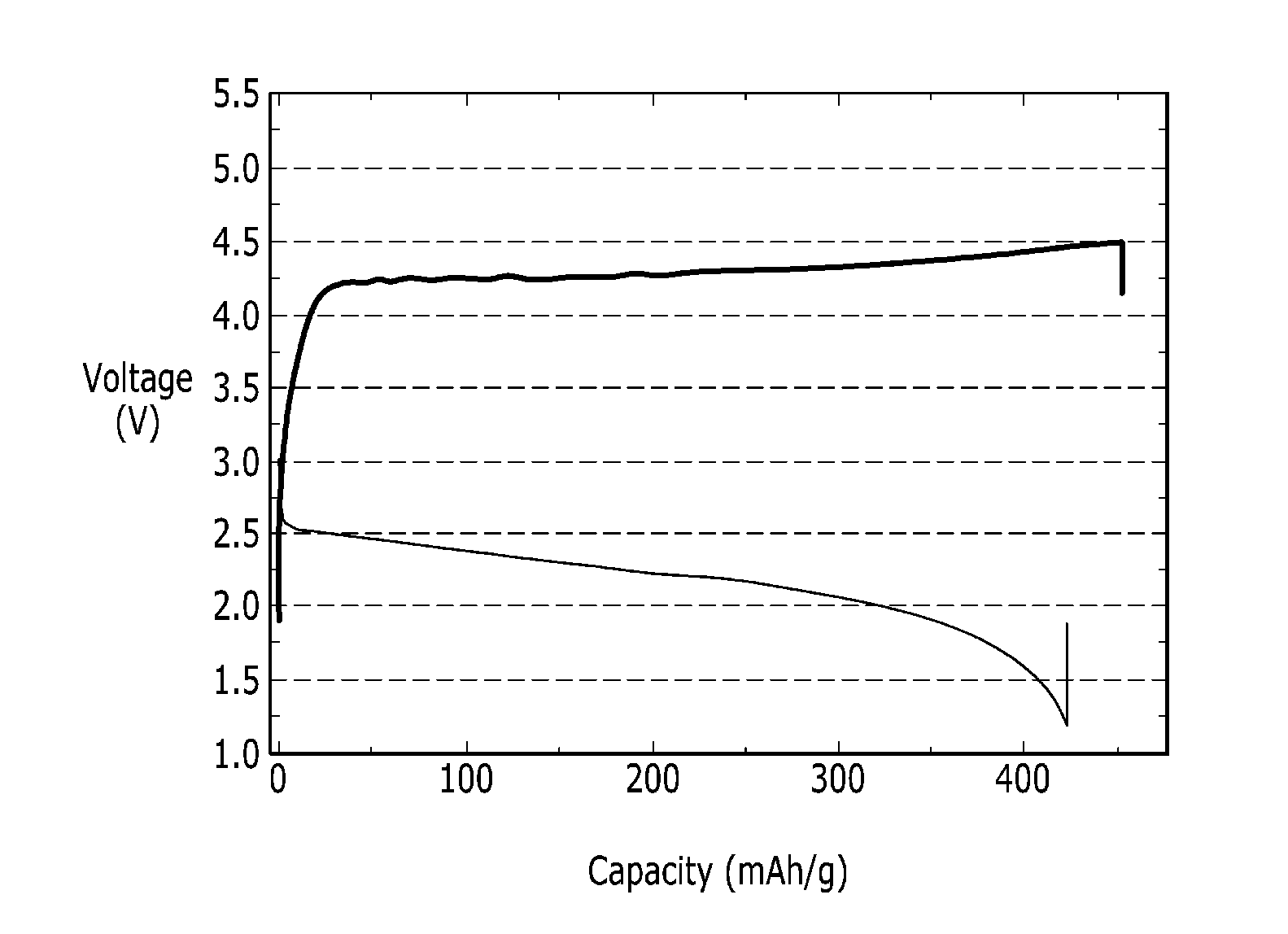
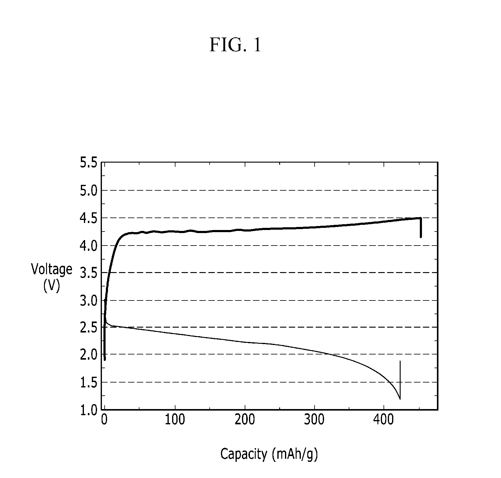
[0077]The lithium air battery cells according to Examples 1 and 2 and Comparative Examples 1 and 2 were evaluated regarding charge and discharge characteristics to evaluate electrochemical performance. The results are provided in FIGS. 1 to 4.
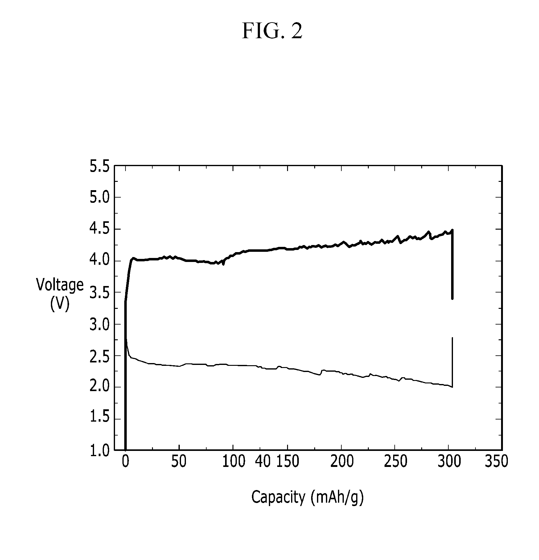
[0078]The lithium air battery cell according to Example 1 was put in a chamber filled with oxygen and charged and discharged once at 1.2 to 4.5 V under a current condition of 10 mA / g. In addition, the lithium air battery cell according to Example 2 was charged and discharged once at 2.0 to 4.5 V under a current condition of 5 mAh / g. Furthermore, the lithium air battery cells according to Comparative Examples 1 and 2 were charged and discharged once at 2.0 to 4.1 V under a current condition of 10 mAh / g.
[0079]FIG. 1 is a graph showing charge and discharge characteristics of the lithium air battery cell according to Example 1, FIG. 2 is a graph showing charge and discharge characteristics of the li...
PUM
 Abstract
Description
Claims
Application Information