Enhanced methods for solvent deasphalting of hydrocarbons

a hydrocarbon and solvent technology, applied in the field of hydrocarbon solvent deasphalting, can solve the problems of limiting reliability, high solvent requirement of the process, and inability to arrange, and achieve the effect of enhancing mass transfer

Inactive Publication Date: 2013-04-25
MEG ENERGY CORP
View PDF8 Cites 17 Cited by
  • Summary
  • Abstract
  • Description
  • Claims
  • Application Information

AI Technical Summary

Benefits of technology

[0034]A Mixing Enabled Precipitator (MEP) in one embodiment supports a continuous process to completely and rapidly mix two different viscosity fluids with the magnitude of viscosity difference being at least 100,000. The MEP of an embodiment provides enhanced mass transfer to accelerate precipitation of solid asphaltenes by changing the solubility characteristics of the asphaltene particles in the blended stream from the heavy hydrocarbon stream for downstream separation.

Problems solved by technology

It is burdened by plugging if any appreciable solid asphaltenes are present as in asphaltene-rich streams like bitumen, and the process has a high solvent requirement.
This arrangement is not feasible if the asphaltene particles that have settled out in the extractor are in a solid form in the solvent at the process operating temperature.
Solid particles plug the spray drier nozzle limiting reliability and thus viability of this scheme in solid asphaltene rich streams.
The remaining asphaltene remains wet and sticky and has not enough solvent left to keep the heavy bituminous phase (with many solids) fluid.
This process is designed to handle a rich asphaltene stream that has solid particles but is a highly costly process since the separation of the solids is done through a solid / liquid separation with additional solvent needed to make the material flow to the decanter.
The recovered solvent vapour then needs to be condensed for re-use, which is another high energy step adding complexity.
The challenge with flash / spray driers such as disclosed here using liquid solvent as a transport media is the propensity for the asphaltenes generated in the integrated process to remain wetted before, during and after a flash drying phase.
Wetted asphaltene sticks to surfaces and fouls and plugs process equipment.
The reduced reliability inherent in this approach makes such operations costly for heavy crudes with high asphaltenic content.
However, the process is burdened by the many required process steps to get both the DAO product and the dry asphaltene product.
In addition, the operating conditions required to generate the solid asphaltenes in the decanting step do not work for Canadian bitumen.
No savings in processing steps are made and an additional material is added increasing the complexity of operation.
The separated asphaltene-rich stream from the ROSE SDA unit is a liquid solution which is very sticky and requires extreme operating conditions (high temperatures) and added solvent to facilitate feedstock flow through the process equipment which is very intensive and expensive.
This process does not put the solid asphaltenes through a mild thermal cracking process, and thus does not convert the asphaltenes from a sticky to a crunchy texture, and relies primarily on excess solvent to transport the asphaltene stream in a diluted form.
In this set up, a large portion of the original feedstock is downgraded from crude and sent to a low conversion (i.e. coker, gasification) or low value operation (asphalt plant) reducing the overall economic yield of the crude (in addition to the relatively high process intensity of the operation).
In addition, these long side chains readily entangle with other similar molecules to make large unmanageable sticky clumps.
Adding direct, intense, instantaneous heat to these sticky clumps generates substantial quantities of coke and light gases.
Rapid cooling creates condensation reactions generating differently configured complex asphaltenes with long side chains that are just as difficult to deal with further downstream in the processing.
The U.S. Pat. No. 4,454,023 patent provides a means for upgrading lighter hydrocarbons (API gravity>15) than Canadian Bitumen but is burdened if used with Canadian Bitumen by the misapplication of thermal cracking that will over-crack and coke the hydrocarbon stream, as well as by the complexity and cost of an additional solvent extraction stage to separate the resin fraction from the DAO.
Recycling part of the resin stream is required to produce a product which meets pipeline transportation specifications and increases the operating costs and complexity and process intensity of the operation.
Typical thermal crackers, like visbreakers, do not appreciably improve the characteristics of the complex Canadian Bitumen asphaltene molecules.
The high-cost solvent is consumed in the gasifier, increasing the capital and operating cost of the entire operation while also increasing the carbon footprint of the process and the process intensity.
When viscosities of the streams differ by factors of greater than 1000, static mixers do a poor job of mixing the streams.
In addition, for processes with a stream or streams having a high propensity to foul, such as a modified-asphaltene stream, static mixers create a flow restriction point, added surface area and irregular wall features exposed to the stream, and increase the probability of fouling.
However, due to the large viscosity differences between the heavy crude and solvent (well over a factor of 1000 difference), a static mixer in this application does not provide any noticeable benefit.
After a nominal settling time, the gas will liberate from the crude especially under warmer temperatures, thus impacting RVP (Reid vapour pressure) on the crude thereby limiting the benefit of this application of shear mixing in crude refining and with a resulting increase in a two-phase fluid which is unsuitable for pipeline transport and pumping.
The precipitated asphaltenes easily foul the rotating disks in the Foster Wheeler process within the extractor vessel.

Method used


Image

  • Enhanced methods for solvent deasphalting of hydrocarbons
  • Enhanced methods for solvent deasphalting of hydrocarbons
  • Enhanced methods for solvent deasphalting of hydrocarbons

Examples


Embodiment Construction

[0037]The detailed description set forth below in connection with the appended drawings is intended as a description of various embodiments of the present invention and is not intended to represent the only embodiments contemplated by the inventor. The detailed description includes specific details for the purpose of providing a comprehensive understanding of the present invention. However, it will be apparent to those skilled in the art that the present invention may be practiced without these specific details.

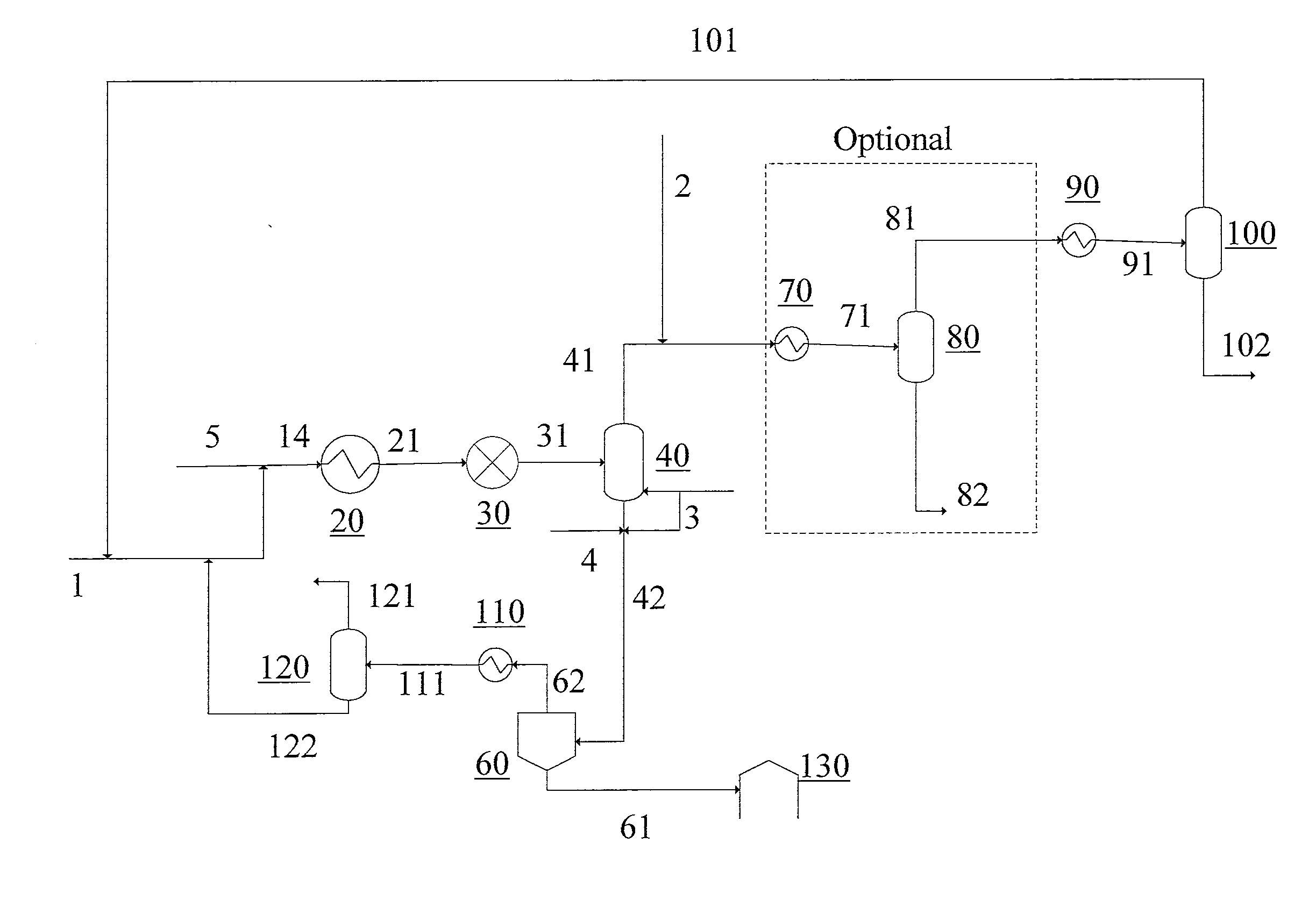
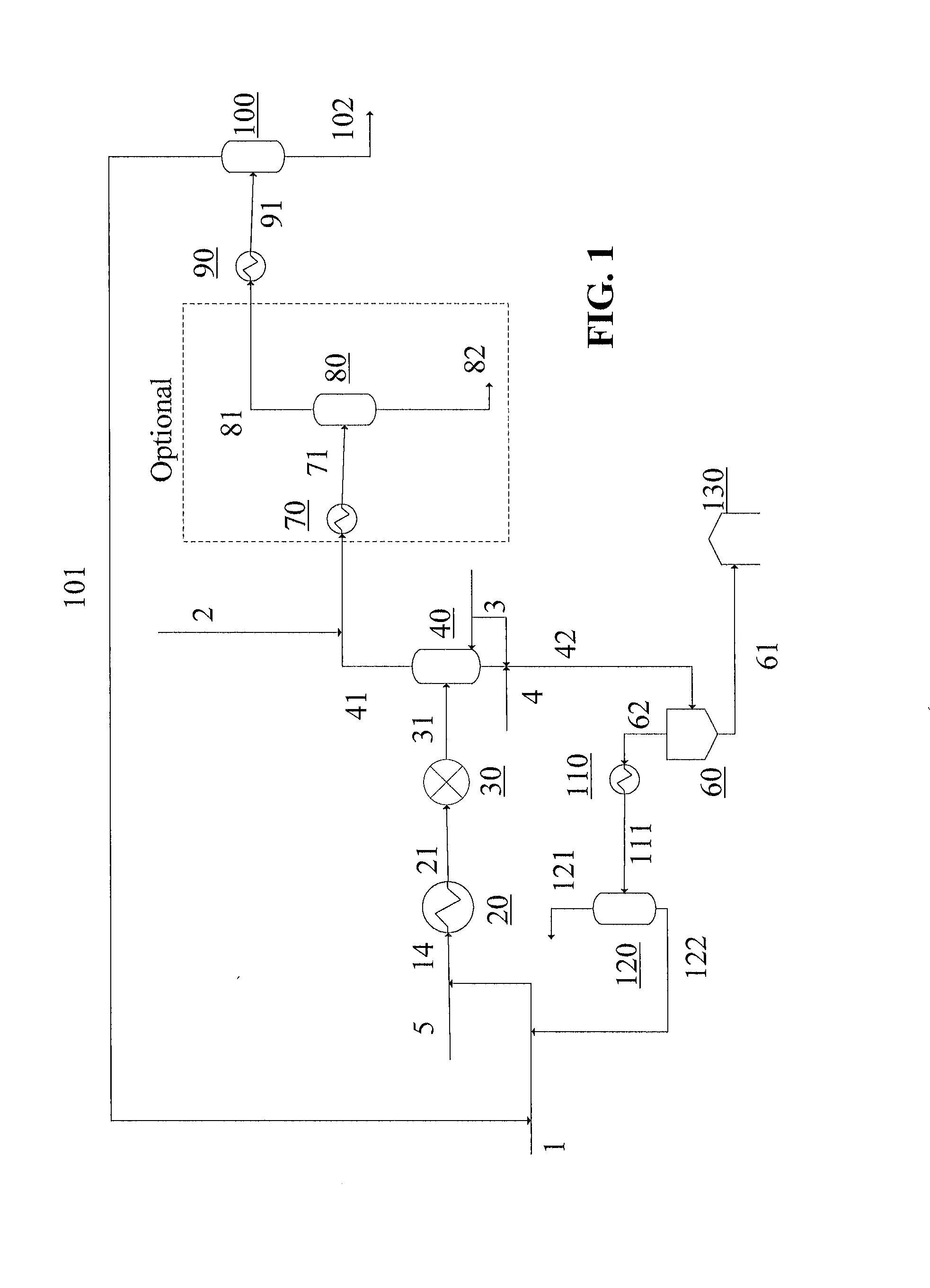
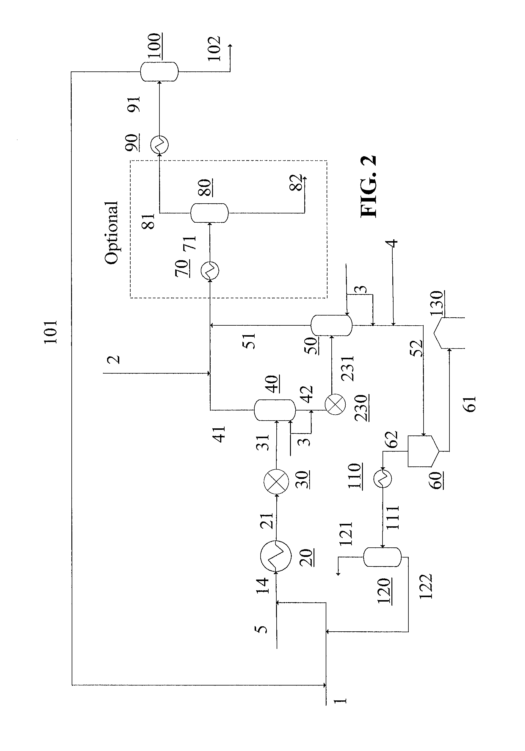
[0038]FIG. 1 is a process flow diagram depicting an improved SDA process, using an open-art SDA process with addition of a Mixing Enable Precipitator (MEP) 30, applied to a heavy hydrocarbon (ex. Canadian Bitumen) stream 5 to effect mixing with a solvent to create a blended hydrocarbon suitable as refinery and pipeline feed from various combinations of product streams 82, 100 and 102.

[0039]Fresh solvent make-up is added in a stream, 1, and recycled solvent from the process th...


PUM

PropertyMeasurementUnit
operating temperatureaaaaaaaaaa
operating pressureaaaaaaaaaa
temperatureaaaaaaaaaa

Abstract

Improvements to open-art Solvent Deasphalting (SDA) processes have been developed to reduce capital and operating costs for processing hydrocarbon streams are provided whereby open art SDA scheme is modified to include appropriately placed mixing-enabled precipitators (MEP's) to reduce solvent use requirements in an asphaltene separation step and to increase overall reliability for SDA processes, particularly suitable for Canadian Bitumen. When integrated with a mild thermal cracker, the improved SDA configuration further improves crude yield to be pipeline-ready without additional diluent and for use to debottleneck existing facilities such as residue hydrocrackers and coking units.

Description

[0001]This application claims the benefit of U.S. provisional patent application No. 61 / 548,915 filed Oct. 19, 2011.FIELD OF THE INVENTION[0002]This invention has to do with improving produced bitumen, focusing on (but not limited to) Canadian bitumen, by a novel post-production process improving deasphalting in particular.DESCRIPTION OF PRIOR ARTPrior Art SDA Schemes:[0003]Solvent Deasphalting (“SDA”) is a process employed in oil refineries to extract valuable components from residual oil from a prior operation. The extracted components can be further processed in refineries where they are cracked and converted into valuable lighter fractions, such as gasoline and diesel. Suitable residual oil feedstocks which can be used in solvent deasphalting processes include, for example, atmospheric tower bottoms, vacuum tower bottoms, crude oil, topped crude oils, coal oil extract, shale oils, and oils recovered from oil sands.[0004]Solvent Deasphalting processes are well known and described...

Claims


Application Information

Patent Timeline
Patent Type & Authority Applications(United States)
IPC IPC(8): B01D11/04C10G57/00C10C3/16
CPCC10G55/04C10G2300/4056C10G9/00C10G2300/44C10G21/003C10G2300/206
Inventor CORSCADDEN, TOMBRUCE, GERALDDIDUCH, GREGHOCKING, DAMIENREMESAT, DARIUS
Owner MEG ENERGY CORP
Why Eureka
Try Eureka