Impregnation Assembly and Method for Manufacturing a Composite Structure Reinforced with Long Fibers

Inactive Publication Date: 2013-05-09
3B FIBERGLASS
View PDF0 Cites 15 Cited by
  • Summary
  • Abstract
  • Description
  • Claims
  • Application Information

AI Technical Summary

Benefits of technology

The present invention relates to a spreader assembly for compressed air flow in fiber strands. The assembly includes multiple spreader units with passageways for filaments. The air pressure is applied at an angle, perpendicularly to the fiber strands through small holes at the air outlet. The air pressure is selected based on the strength of the links between individual fibers. The assembly allows for simultaneous treatment of multiple fiber strands by creating a divergent air stream that breaks up the links between individual filaments and spreads them widely and uniformly. The invention is suitable for manufacturing composite structures with reinforcing fibers and wide composite bands. The assembly can be stacked with more than one spreader unit, and each unit has parallel passageways for filaments placed in a lateral direction to avoid overlapping. The cover of each spreader unit has air passages connected to the passageways for filaments. The technical effects of the invention include improved fiber spreading and uniformity, enhanced air pressure utilization, and efficient composite structure manufacturing.

Problems solved by technology

Another disadvantage of open bath is, that the strands soaked with resin are generally squeezed under friction to remove excess resin picked up by the strands.
Over time, the squeezing friction can lead to filament rupture, thus creating fuzz in the bath and, thereby, hindering smooth wetting of fibers.
Also, resin tends to build up on the squeezer and to becomes cured and hard, hence causing fiber breaks.
Further, the big open baths pose difficulties in controlling the pot life of the thermosetting impregnating formulation leading to inconsistent viscosity and wetting of the strands.
Also, squeezing out the excess resin mix from the soaked strands has a tendency to limit the achievable fiber to matrix ratio which may not be optimum.
Although thermosetting composites provide many advantages, once cured, they can no longer be softened, reshaped or given curve.
In the case of thermoplastic compositions, however, it is usually more difficult to advantageously impregnate the reinforcing material because of comparatively higher viscosities.
Products with insufficiently wetted fibers can result in poor quality composites, e.g., lacking mechanical strength and aesthetic properties.
Generally, the quality and performance of the part are affected when such processes are run at higher speeds.
Namely, due to the much higher viscosities of thermoplastic material, it cannot be adequately penetrated and distributed throughout the strand at high production speed thus leading to unacceptable dispersion of the fibers in the subsequently processed product.
During laying up, consolidation and compaction, air may get trapped in interlayers.
Also, intermingling of resin molecules of two layers may require higher heat, compaction pressure and longer processing time.
According to such techniques composite parts can be made at higher rates, but such two-step processes suffer from cost disadvantages, extra thermal history, handling, processing problems and quality issues for the final part to be obtained and seriously limit the flexibility for the users in the formulation package, color and amount of fibers.
In either case, the solvent must be driven off after the impregnation step, resulting in an additional step in the process as well as in an unwanted emission.
Moreover, the desired matrix may be insoluble in commonly used solvents or difficult to transform into particle form.
The technique, however, has the disadvantage that the fiber strand risks to be coated only from the outside with no appreciable impregnation of the fiber bundle occurring with the matrix resin in the cross-head die.
Therefore this technique is not suitable to obtain good in-line impregnation of continuous fibers.
In order to improve the fiber dispersion in the final part, such reinforced pellets require molding at higher shear, but that can lead to fiber breakage, fiber length shortening and, therefore, to reduce mechanical performance.
If a compacted fiber bundle is passed through this assembly without friction applied, the expected impregnation quality is poor.
The long meandering curved passage, may allow more contact time and surface between impregnating material and fibers, but can also lead to more friction and thus higher pulling forces and tension, thus increasing the risk of filaments rupture during impregnation.
This higher friction in the passage does not allow increase of line speeds without affecting the production and the impregnation quality.
The combination of friction and tension forces on the fibers, particularly at high temperatures in the hot-melt matrix, may cause fiber breakage leading to fuzz generation.
Also, higher tensions can cause the strand to break.
Fuzz generation may ultimately lead to die blocking, requiring regular maintenance which in turn affects production costs.
Consequently, conventional processes for impregnation by exposing a fiber reinforcing material to friction and high pulling force in a hot-melt viscous matrix have deficiencies which tend to limit the quality of the product or the speed of manufacturing.
The problems become even more severe at higher production speeds or with higher content of reinforcing materials.
Therefore, such processes may only be run at much lower and uneconomical speeds.
Furthermore, the speed of the process is hindered or limited by the degassing step of the process.

Method used


Image

  • Impregnation Assembly and Method for Manufacturing a Composite Structure Reinforced with Long Fibers
  • Impregnation Assembly and Method for Manufacturing a Composite Structure Reinforced with Long Fibers
  • Impregnation Assembly and Method for Manufacturing a Composite Structure Reinforced with Long Fibers

Examples


example 1

[0151]The impregnation system according to the present invention has been used to impregnate continuous fibers with a thermoplastic polymer at high line speed and provide a composite structure in which the reinforcing continuous fibers are uniformly distributed.

[0152]Commercial glass fiber direct roving (GFDR) SE4220 from 3B-Fibreglass was used as glass fiber strand input, made up of 19μ diameter filaments giving tex (g / km) of 3000. Each GFDR was placed on a free rotating disc mounted on a table to enable easy strand pulling. The unwinding of the GFDR was from outside to avoid any twists during unwinding. Total of six direct roving were used simultaneously for impregnation.

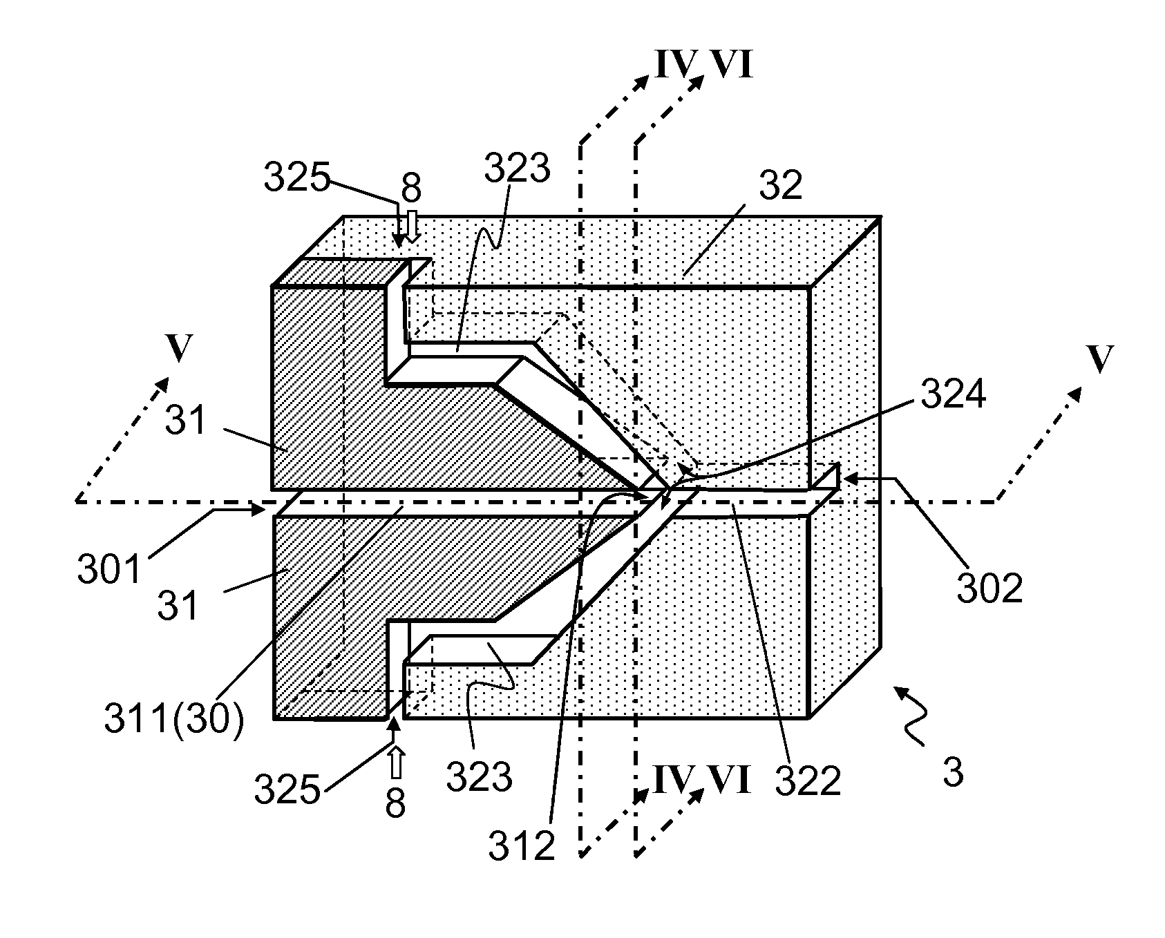
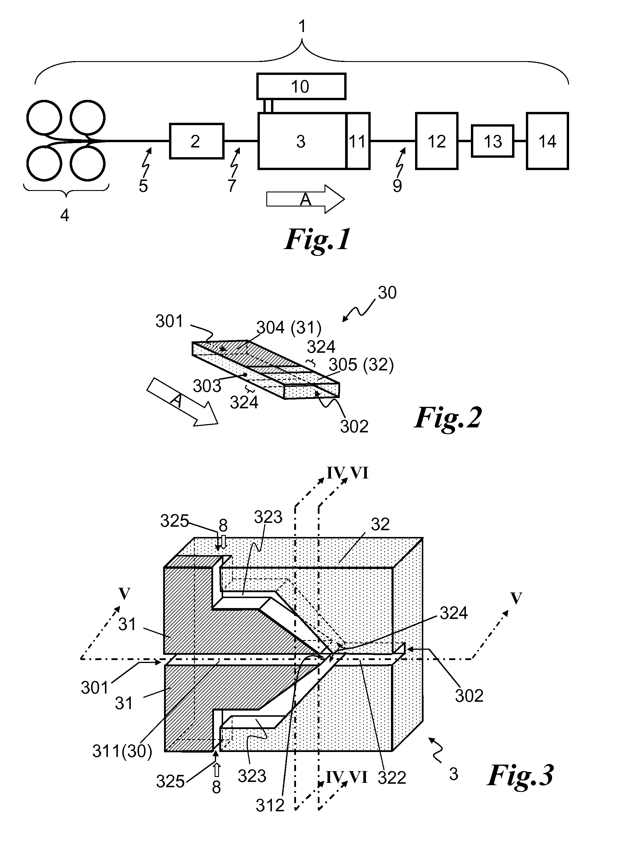
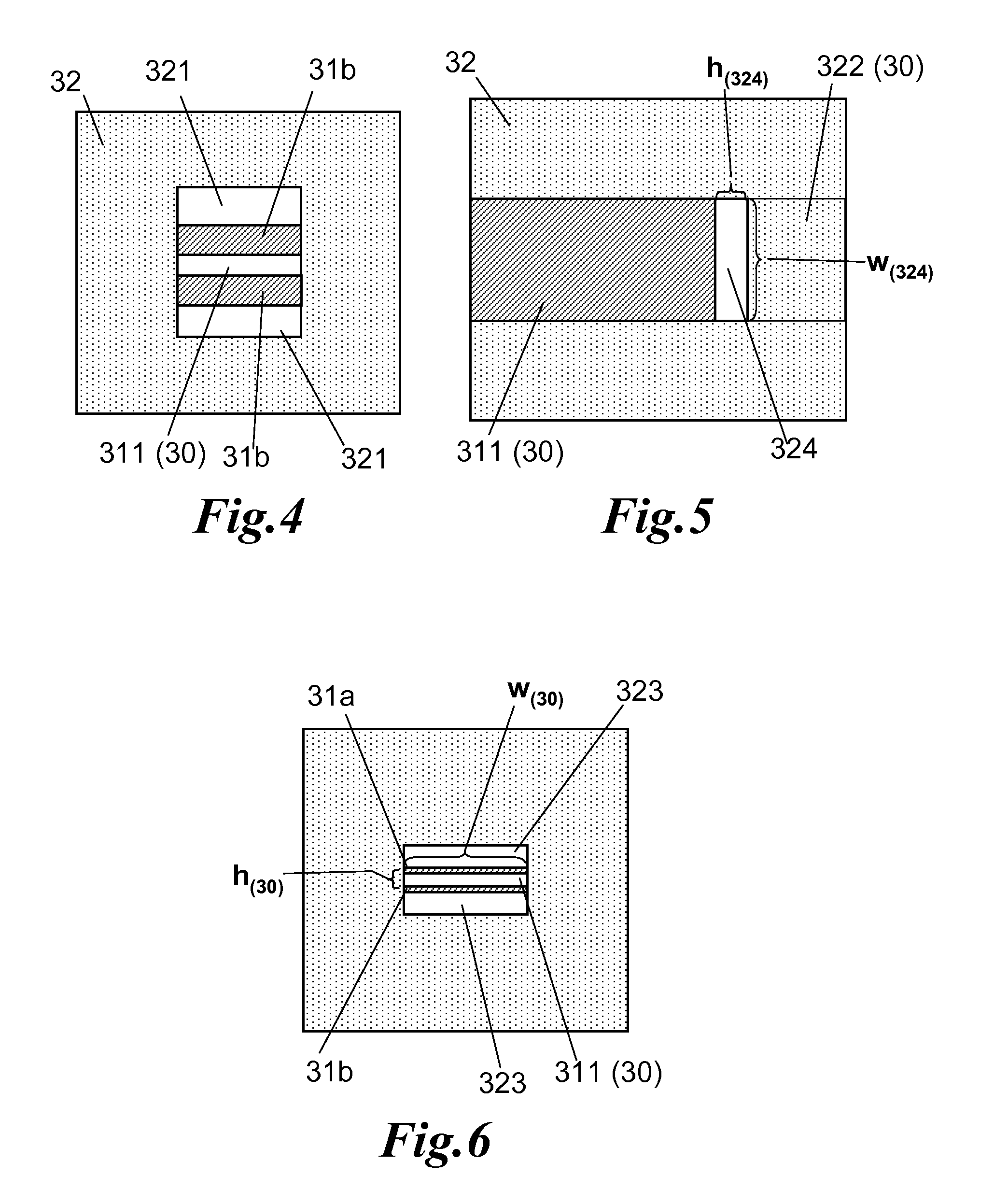
[0153]A spreader assembly unit according to the present invention was arranged in six channels, enabling six inlets for glass fiber strands from six direct rovings as shown in FIGS. 37 to 45. Each strand went through one inlet entrance of 6 mm×0.5 mm, which was also the start of the rectilinear part of the channel...

example 2

[0156]Like in example 1, same spreader assembly and impregnation die according to the invention have been used except that the impregnating substance was a proprietary Polyolefin composition with MFR around 15 g / 10 min (190° C., 2.16 kg) with Mp around 128° C. The extruder was set to supply around 245-250 cm3 / min of molten thermoplastic feed to the impregnation die attached to its exit and fiber puller speed of 20 m / min. After passing over the two ceramic rolls, maintained at 250° C., a tape with average width of 65 mm and average thickness around 0.29 mm after cooling was obtained with a glass content of around 62% by wt. The microscopic (Phenom Microscope that was coupled high quality scanning electron microscope with optical camera from FEI Company, USA) pictures reveal good fiber dispersion within the thermoplastic matrix resin as shown in FIG. 51.

example 3

[0157]Like Example 1, the same impregnation die has been used but the spreader assembly of the invention was chosen with four channels to give a spread fiber band width of 60 mm. Thus, four strands of glass fiber direct roving were used. The extruder was set to supply around 285-290 cm3 / min of molten thermoplastic feed to the impregnation die attached to its exit and fiber puller speed of 30 m / min. After passing over the two ceramic rolls, maintained at 250° C., a tape has been obtained that showed an average width of 46 mm and an average thickness of around 0.3 mm after cooling, with a glass content around 58% by wt. The microscopic (Phenom Microscope that was coupled with high quality scanning electron microscope with optical camera from FEI Company, USA) pictures reveal good fiber dispersion within the thermoplastic matrix resin as shown in FIGS. 52 and 53.


PUM

PropertyMeasurementUnit
Angleaaaaaaaaaa
Angleaaaaaaaaaa
Angleaaaaaaaaaa

Abstract

The present invention provides an impregnation system suitable for impregnating filaments continuously with an impregnating substance, said system may comprise an impregnation assembly comprising (a) at least one axial passageway for the filaments having an entrance end and an exit end and (b) at least one passageway for the impregnating substance having at least one inlet for the impregnating substance and at least two outlets for the impregnating substance leading into the passageway for the filaments via the outlets for the impregnating substance, wherein the passageway for the filaments has an oblong cross-section at the outlet point for the impregnating substance, and the at least two outlets for the impregnating substance have an oblong cross-section, and are disposed essentially opposite to each other, at the opposite widths of the passageway for the filaments. Thus, the present invention proposes an in-line system for manufacturing continuous fiber reinforced thermoplastic structure which comprises a simple device to provide strands in spread filaments form without using high friction or tension on the strand or filaments so as to ease the impregnation step and to allow higher line speeds and lower cycle times.

Description

TECHNICAL FIELD[0001]The present invention relates to an impregnation assembly and a method for manufacturing continuous fiber reinforced composite structures, which provides improvements in productivity and product properties such as quality, aesthetics and flexibility, as well as environmental and cost advantages. More particularly, the invention relates to a new cross-head die assembly designed for impregnating continuous filaments or fibers with an impregnating substance such as a polymer matrix. The present invention also relates to a thermoplastic composite such as a prepreg, reinforced with continuous fibers such as glass, carbon or graphite fibers, which is suitable for use in a subsequent processing with cost, speed and environmental advantages. The present invention particularly relates to a method and system which uses an impregnation means comprising a step of sandwiching the multi-filaments with two portions of the impregnating substance at the initial meeting point of ...

Claims


Application Information

Patent Timeline
IPC IPC(8): B05C3/12B29C53/16B05D1/18B32B5/16B32B27/12B29C48/05B29C48/32
CPCB29B15/122B29C47/0014B29C47/0019B29C47/0023B29C47/02B29B15/12B29C47/20B29C70/523B29C70/543B29B15/14B29C47/025B29C48/05B29C48/15B29C48/07B29C48/09B29C48/154B29C48/32Y10T428/249921D01D11/02D02J1/18B65H51/005
Inventor KASHIKAR, SANJAY P.
Owner 3B FIBERGLASS
Why Eureka
Try Eureka