Method and device for controlling effective heat transfer in a solid gas storage system
a solid gas storage and effective heat transfer technology, applied in the direction of machines/engines, energy input, separation processes, etc., can solve the problems of difficult to achieve under driving conditions, inconvenient and indirect methods for mobile transportation of ammonia, and too hazardous ammonia storage in a vessel. achieve the effect of reducing pressur
- Summary
- Abstract
- Description
- Claims
- Application Information
AI Technical Summary
Benefits of technology
Problems solved by technology
Method used
Image
Examples
example 1
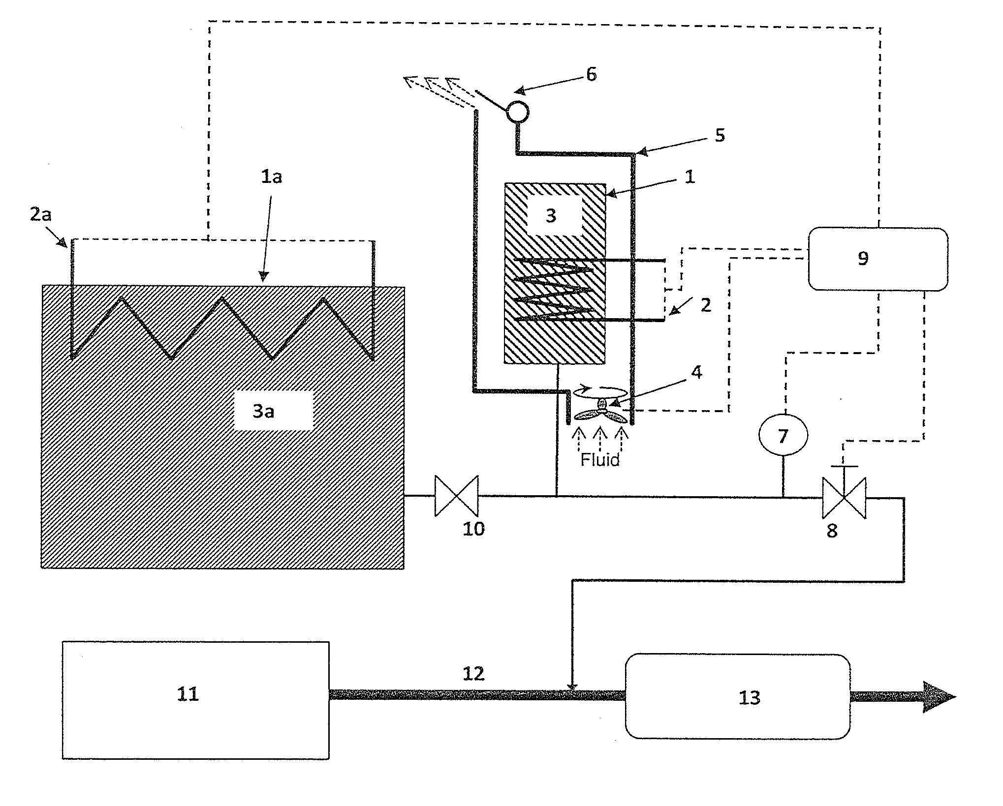
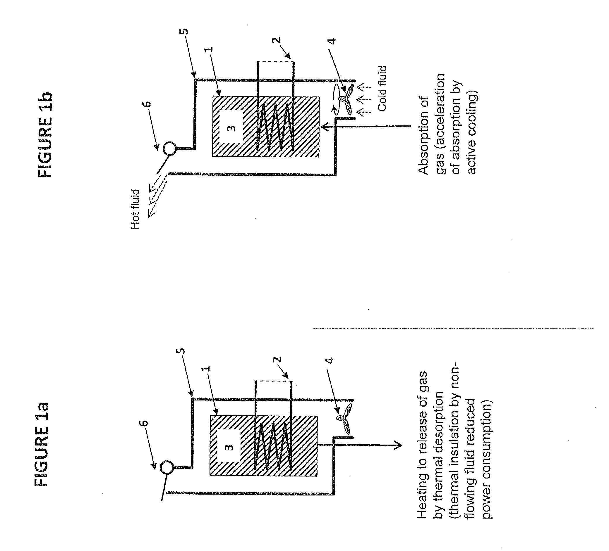
[0078]A small storage unit of approx. 500 ml with Sr(NH3)8Cl2 is partly degassed of, i.e. some of the material is Sr(NH3)8-nCl2 where n∈[1, 2, . . . , 8]. The storage unit 1 is placed at room temperature and it is exposed to ammonia from a pressurized source giving an elevated pressure. Two experiments are made: a) one where there is no encapsulation 5 or fluid flow device 4 and therefore only passive cooling by normal natural convection around the warm unit (i.e. slow heat transfer without a convection gap) and b) one where there is active cooling by forced convection from a blower 4. The ammonia absorption in the two cases are dramatically different:[0079]passive cooling by normal natural convection: 10.2 g NH3 is absorbed from the pressurized source.[0080]active cooling by a small blower: 18.1 g is absorbed from the pressurized source.
Thus, it is seen that slow cooling by natural convection without a convection gap (which will always be a possible heat transfer mechanisms of e.g....
example 2
[0081]During normal operation of a small storage unit 1, the power for operating the unit, heating 2, consist of two parts: heat for releasing ammonia and heat loss to the surroundings. Assuming the unit 1 has a surface area of 0.03 m2 and is operated on a vehicle that drives on the road. Without the insulation by an air gap around the unit 5, the forced convection caused by the cold air (e.g. 5° C.) flowing around the unit gives a heat loss from the 50° C. surface temperature of the unit 1 of approx.:
(55° C.-5° C.)*30 W / m2 / ° C.*0.03 m2=45 W.
(assuming heat transfer coeff. of 30 W / m2 / ° C.
If the unit according to the invention is less exposed to the environment during operation the heat loss could be reduced to:
(55° C.-5° C.)*5 W / m2° C.*0.03 m2=7.5 W
(assuming heat transfer coeff. of 5 W / m2 / ° C.
This would have a non-negligible influence on the power withdrawn from the battery or generator of the vehicle.
[0082]Thus, it is demonstrated that embodiments according to the invention has both...
example 3
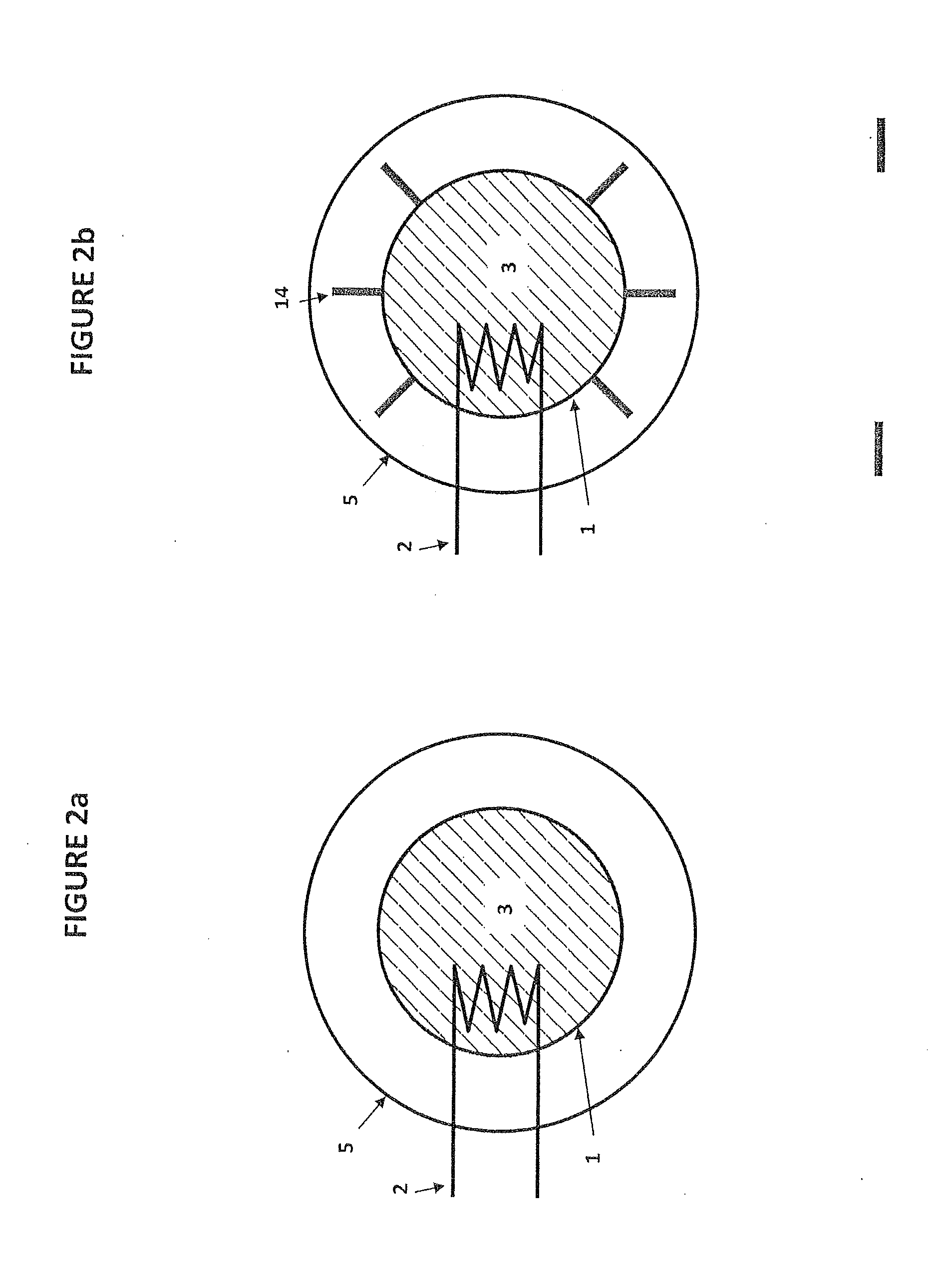
[0083]A small storage unit 1 of approx. 500 ml is kept in an encapsulation 5 made of either metal or e.g. injection-molded plastic / polymer (a polymer further reduces the heat loss from the encapsulation). One end of the encapsulation is equipped with a small fan 4—similar as inexpensive blowers for computers—with a diameter of 4 cm. Such a small blower may use less than 1 W and still create a flow of 10 m3 air per hour (=10000 [liter / hr] / 24.5 [liter / mol] / 3600 [s / hr]=0.113 mol / s) through the annular gap of e.g. 0.5 cm around the unit 1.
[0084]Air (or calculated as N2) with heat capacity of approx. 20 J / mol / K flows around a unit 1 during absorption and the temperature of the air flow increases by 20K (from e.g. 298K to 318K). The heat transfer from forced convection created by the fan 4 is then approx.:
0.113 [mol / s]*20 [K]*20 [J / mol / K]=45.4 W.
[0085]The absorption enthalpy of ammonia is approx. 42 kJ / mol NH3 and with a cooling rate of 45.4 W, then a flow of ammonia of 1.08*10−3 mol NH3 / ...
PUM
| Property | Measurement | Unit |
|---|---|---|
| Temperature | aaaaa | aaaaa |
| Pressure | aaaaa | aaaaa |
| Heat | aaaaa | aaaaa |
Abstract
Description
Claims
Application Information
 - R&D
- Intellectual Property
- Life Sciences
- Materials
- Tech Scout
- Unparalleled Data Quality
- Higher Quality Content
- 60% Fewer Hallucinations
Browse by: Latest US Patents, China's latest patents, Technical Efficacy Thesaurus, Application Domain, Technology Topic, Popular Technical Reports.
© 2025 PatSnap. All rights reserved.Legal|Privacy policy|Modern Slavery Act Transparency Statement|Sitemap|About US| Contact US: help@patsnap.com


