Ophthalmic lens containing a fresnel surface and method for manufacturing same

a technology of fresnel and lens, which is applied in the direction of manufacturing tools, instruments, food shaping, etc., can solve the problems of inability to fill the mold with straight injection molding, inability to manufacture thin lenses with conventional injection molding, and inability to control the thermodynamics of cooling melt flow, etc., to achieve high adhesion, low adhesion, and high heat conductivity

Active Publication Date: 2013-05-16
ESSILOR INT CIE GEN DOPTIQUE
View PDF3 Cites 23 Cited by
  • Summary
  • Abstract
  • Description
  • Claims
  • Application Information

AI Technical Summary

Benefits of technology

[0028]According to another embodiment, there is provided a system for manufacturing an ophthalmic lens containing a Fresnel surface inside the lens. The system includes an injection molding machine containing a microstructured mold insert in combination with two thermoplastic articles. A first thermoplastic lens has a Fresnel surface molded b...

Problems solved by technology

The paths from the gate to the edge points of the mold cavity are not symmetrical and therefore make it difficult to control the thermodynamics of the cooling melt flow.
As lens cavities become thinner, straight injection molding techniques are unable to fill the mold without premature freeze-off.
As described above, thin lenses cannot be made with conventional injection molding, because of issues relating to mold replication.
Similarly, microstructured surfaces which are more challenging, cannot be replicated completely and precisely using a structured metal insert in an injection molding process.
The proposed methods are costly in that they involve multipl...

Method used


Image

  • Ophthalmic lens containing a fresnel surface and method for manufacturing same
  • Ophthalmic lens containing a fresnel surface and method for manufacturing same
  • Ophthalmic lens containing a fresnel surface and method for manufacturing same

Examples


example 1

PMMA Overmolded onto Fresnel PC Lens

[0111]The typical processing conditions is listed in Table 8. Two parameters, melt temperature and mold temperature, were tested systematically (Table 9), to see their effects on microstructure filling, rounding and deformation.

TABLE 8General processing condition for PMMAParametersMelt Temperature (° F.)460Injection Speed (mm / s) 25Holding Pressure (bar)Multi steps from1000 to 150 barHolding Time (s) 9Cooling Time (s)220Mold Temperature (° F.)131

TABLE 9Test matrix for melt temperature and mold temperatureMelt Temperature (° F.)470460450440430420410 Mold111xxxxTemperature131xxxxxx(° F.)151xxxxx represents conditions being tested.

[0112]1.1 Melt Temperature Effect

[0113]The melt temperature should be set above 400° F. Otherwise, delamination will occur.

[0114]The microstructures were filled quite well, at all tested temperatures (410 to 470° F.).

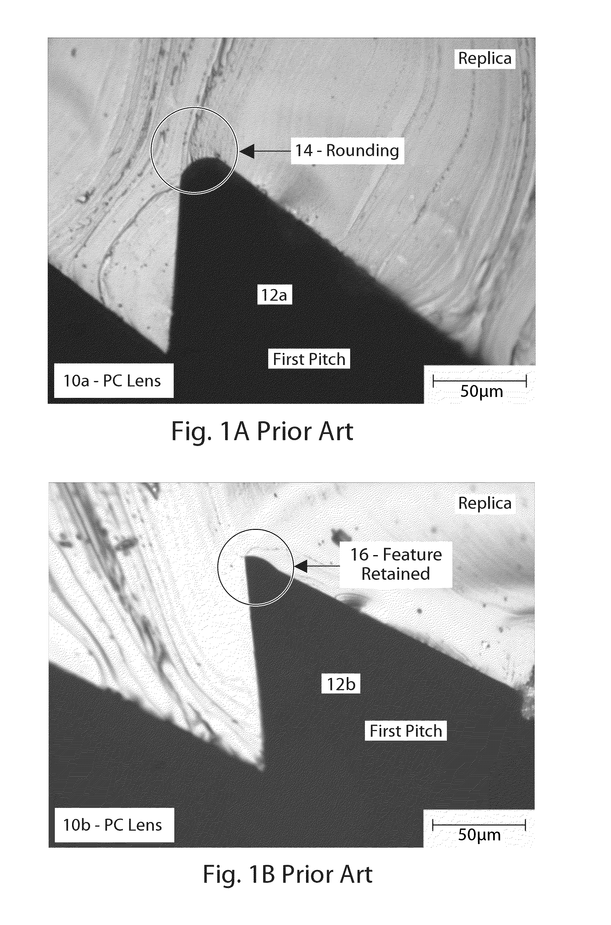
[0115]The microstructure tips were rounded at edge location of Fresnel PC lens at all tested melt temperature...

example 2

TPU Overmolded onto PC Fresnel Lens

[0124]

TABLE 10Typical processing condition for TPU overmoldingParameterInjection speed (mm / s)10Injection pressure (bar)900Switch over (mm)7.5Holding Pressure (bar)Multi steps from700 to 100 barHolding Time (s)3Barrel Temperature (° F.)360Mold Temperature (° F.)150Dosage (mm)30Cooling time (s)150

[0125]The microscopic pictures of cross section of integrated TPU / Fresnel PC lens are shown in FIGS. 8A and 8B, for Fresnel teeth at different locations. FIG. 8A shows the 1st PC tooth 80a at the center of the lens with the adjacent TPU coating 82a. FIG. 8B shows the last PC tooth 80b at the edge of the lens with the adjacent TPU coating 82b. Same results are found as for PMMA / PC lens: (1) The microstructures on Fresnel lens are well filled. (2) No rounding of microstructure teeth. (3) No deformation of microstructure teeth.

[0126]The overall cosmetic aspect of coated Fresnel PC lens is good. No ghost image, or distorted image was observed. No air bubble was ...


PUM

PropertyMeasurementUnit
Temperatureaaaaaaaaaa

Abstract

A process for manufacturing an ophthalmic lens containing a Fresnel microstructured surface inside the lens. The Fresnel lens is injection molded with a mold insert having a heat conductivity lower than the thermoplastic material used to form the Fresnel lens. A second thermoplastic material is overmolded to the Fresnel lens to cover and protect the microstructured surface. The mold insert is made from Nickel or thermoplastic. The resulting lens includes two layers having different refractive indices. The Fresnel lens is made from polycarbonate while the overmold is made from PMMA or TPU.

Description

BACKGROUND OF THE INVENTION[0001]1. Field of the Invention[0002]The invention relates to an ophthalmic lens containing a Fresnel surface and a method for manufacturing same.[0003]2. The Prior Art[0004]Lenses and other articles manufactured at optical quality, have exacting demands for mold replication, high optical transmission and impact resistance. Injection molding of lenses requires edge gating so that the runner ends up remote from the lens surfaces. The paths from the gate to the edge points of the mold cavity are not symmetrical and therefore make it difficult to control the thermodynamics of the cooling melt flow. As lens cavities become thinner, straight injection molding techniques are unable to fill the mold without premature freeze-off. Accordingly, injection molding machines have been modified to enlarge the cavity during some phase of the injection cycle, in a so-called injection / compression process.[0005]For ophthalmic lenses, plastic materials represent a safer, thin...

Claims


Application Information

Patent Timeline
IPC IPC(8): G02C7/02B29C45/14B29D11/00
CPCB29D11/0073B29D11/00269B29C33/3828B29C45/16B29C45/372B29D11/0048B29K2021/003B29K2033/12B29K2075/00B29K2995/0013B29L2011/005
Inventor SHAN, HAIFENGPOUNDERS, MARVINMUISENER, RICHARDHOULE, BILLGOU, ZEMING
Owner ESSILOR INT CIE GEN DOPTIQUE
Why Eureka
Try Eureka