

Method for producing composition for injection molding and composition for injection molding
- Summary
- Abstract
- Description
- Claims
- Application Information
AI Technical Summary
Benefits of technology
Problems solved by technology
Method used
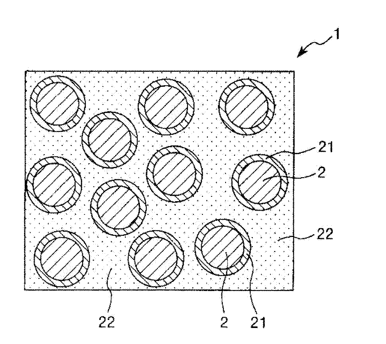
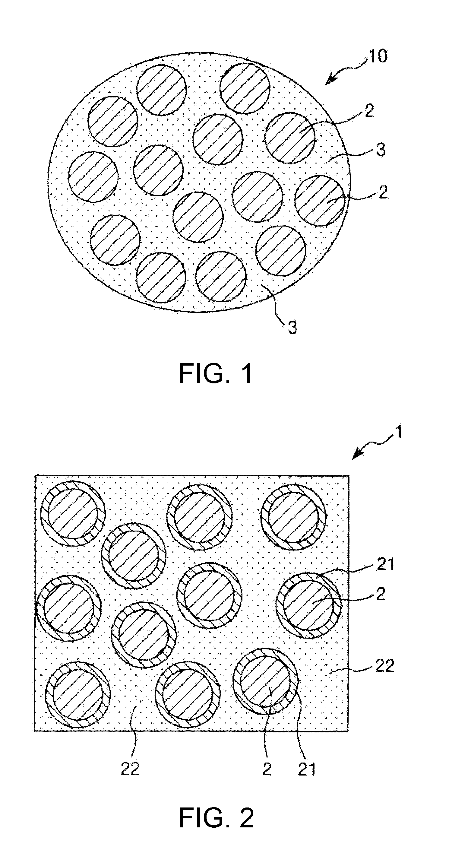
Image

Examples
example 1
[0182]First, an SUS316L powder (powder No. 1) produced by a water atomization method was prepared. The average particle diameter of the SUS316L powder was measured using a laser diffraction particle size distribution analyzer (Microtrac HRA 9320-X100, manufactured by Nikkiso Co., Ltd.). The measured value is shown in Table 1.
TABLE 1AverageAmount of binderparticlewith respect to 100diameterparts by mass ofFormulation[μm]powder (parts by mass)Powder No. 1SUS316L1010Powder No. 22%Ni—Fe69Powder No. 3Ti—6Al—4V1711Powder No. 4Alumina0.530
[0183]On the other hand, a binder having a formulation shown in Table 2 was prepared, and a first resin, a second resin and the like (including a lubricant and another component) were separately cryogenically ground. By doing this, a first powder obtained by cryogenically grinding the first resin, a second powder obtained by cryogenically grinding the second resin and the like were separately produced.
[0184]Specifically, the first resin was placed in a gr...
examples 2 to 19
[0189]Sintered compacts were obtained in the same manner as in Example 1 except that a binder having a formulation shown in Table 2 was used as the binder.
[0190]Incidentally, in Example 15, the kneading temperature was set to 155° C. In the Examples, the average particle diameter of the first powder was about 40 μm or more and 70 μm or less, and the average particle diameter of the second powder was about 180 μm or more and 300 μm or less.
[0191]In Example 10, as the first resin, a mixture of Tenac HC750 and stearyl alcohol was used, and as the second resin, a mixture of E-GA and paraffin wax was used.
TABLE 2MeltingpointClassi-(softeningExam-Exam-Exam-Exam-Exam-Exam-Exam-Exam-ficationComponentpoint)Unitple 1ple 2ple 3ple 4ple 5ple 6ple 7ple 8BinderFirst resinTenac HC750170° C. % by mass9694928781777082Tenac 7520160° C. % by massTenac 7054165° C. % by massSecondE-GMA-VA95° C.% by mass13510152025resinE-GMA-MA52° C.% by mass12E-GMA103° C. % by massE-GA50° C.% by massLubricantParaffin wa...
examples 20 to 22
[0205]First, a 2% Ni—Fe alloy powder (powder No. 2) produced by a water atomization method was prepared. The average particle diameter of the powder was measured using a laser diffraction particle size distribution analyzer. The measured value is shown in Table 1. The formulation of the 2% Ni—Fe alloy is as follows: C (0.4% by mass or more and 0.6% by mass or less), Si (0.35% by mass or less), Mn (0.8% by mass or less), P (0.03% by mass or less), S (0.045% by mass or less), Ni (1.5% by mass or more and 2.5% by mass or less), Cr (0.2% by mass or less), and Fe (remainder).
[0206]Then, sintered compacts were obtained in the same manner as in Example 1 except that a binder having a formulation shown in Table 4 was used as the binder. Incidentally, the molding conditions were set such that the material temperature was 190° C. Further, the degreasing conditions were set such that the temperature was 600° C., the time was 1 hour, and the atmosphere was nitrogen gas (atmospheric pressure). F...
PUM
| Property | Measurement | Unit |
|---|---|---|
| Melting point | aaaaa | aaaaa |
| Melting point | aaaaa | aaaaa |
| Temperature | aaaaa | aaaaa |
Abstract
Description
Claims
Application Information