
Continuous-wave optical stimulation of nerve tissue

a nerve tissue and optical stimulation technology, applied in light therapy, radiation therapy, therapy, etc., can solve the problems of limited knowledge of the risk of injury, and the difficulty in predicting the position and path of the nerve tissue from one patient to another, etc., to achieve the effect of reducing the risk of injury, and improving the quality of li

Inactive Publication Date: 2013-06-27
JUNIVERSITI OF NORT KAROLINA EHT SHARLOTT
View PDF14 Cites 8 Cited by
  • Summary
  • Abstract
  • Description
  • Claims
  • Application Information

AI Technical Summary

Benefits of technology

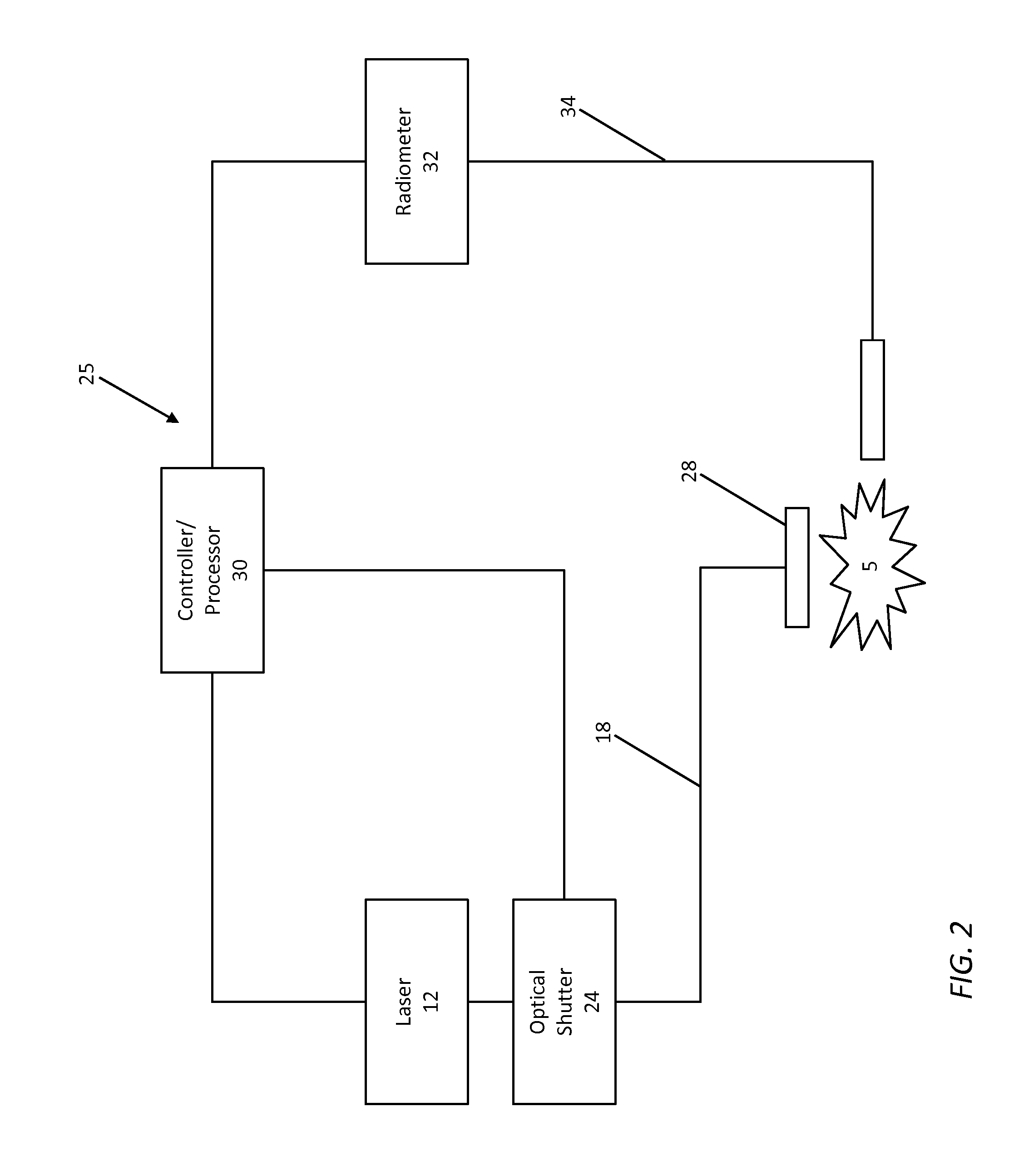
The present invention provides an improved system and method for using laser technology to diagnostically stimulate nerves, such as the CNs of the prostate gland. The invention utilizes a closed-loop feedback system to control the temperature, which prevents damage to the nerves. The system is compact, easy to assemble and use, and allows for efficient and effective stimulation through thin layers of tissue. The use of a CW signal and a collimated beam provides faster and more complete stimulation compared to other systems. The invention can be used for both open and laparoscopic procedures and provides a reliable and accurate tool for diagnosis and treatment of nerve-related diseases. The laser system is calibrated based on temperature and is easy to use with auto-scan applications. The invention incorporates a laser radiation delivery optics and fiber, an optical shutter, an IR detector for temperature measurement, and control and feedback software. The system provides accurate temperature control and can maintain a stable nerve temperature for a short period of time.

Problems solved by technology

Because of the close proximity of the CNs to the prostate surface, beneath a thin fascia layer, they are at risk of injury during the dissection and removal of a cancerous prostate gland.
Their microscopic nature and location beneath this thin fascia layer make it difficult to predict the position and path of the CNs from one patient to another.
Recent anatomic studies also suggest that the CNs may have more extensive branching along the prostate surface than originally thought, and that our current knowledge of the position and path of these nerves may be limited.
However, these electrical nerve mapping devices have proven inconsistent and unreliable in identifying the CNs and evaluating nerve function.
Lack of specificity, high false-positive responses, and the influence of multiple conflicting factors in recording electrical responses during surgery have all been cited as significant limitations of electrical nerve mapping techniques.
First, ENS is limited by the need for physical contact between the electrode and the tissue, which may result in nerve damage.
Second, the spatial precision of ENS is limited by the electrode's size and electrical current spreading in the tissue.
Third, ENS produces electrical artifacts that may interfere with measurement.
Conventional ONS methods, however, require large, powerful, and expensive laser delivery systems, making them impractical for efficient adoption by clinicians.

Method used


Image

  • Continuous-wave optical stimulation of nerve tissue
  • Continuous-wave optical stimulation of nerve tissue
  • Continuous-wave optical stimulation of nerve tissue

Examples


Embodiment Construction

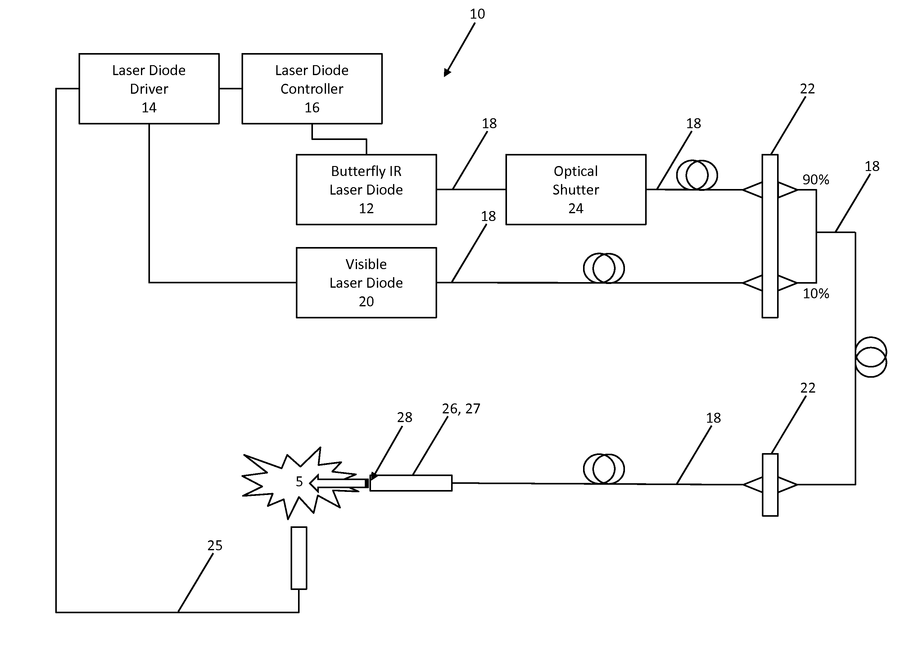
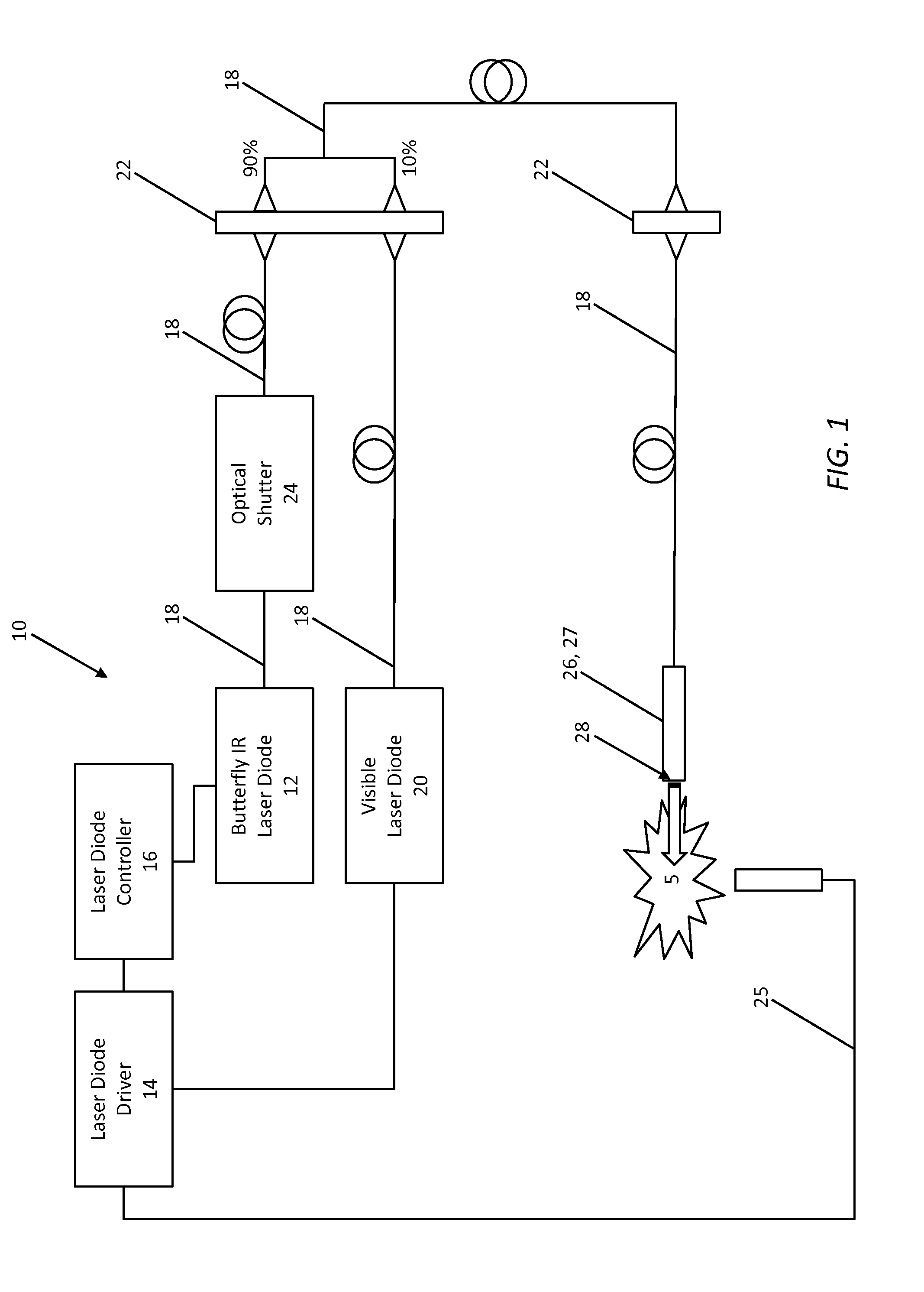
[0019]Referring to FIG. 1, in one exemplary embodiment of the present invention, the CW ONS system 10 includes an IR or near-IR butterfly laser diode assembly 12 or the like that is coupled to a laser diode driver 14 and a laser diode controller 16. Collectively, the laser diode assembly 12, laser diode driver 14, and laser diode controller 16 are operable for delivering CW laser radiation with a wavelength of about 500-3000 nm, preferably with a wavelength of about 1000-2500 nm, and more preferably with a wavelength of about 1000-2000 nm, and most preferably with a wavelength of about 1400-1900 nm, in the IR or near-IR ranges. The laser diode assembly 12 is coupled to one or more lengths of SMF 18 that is / are used to deliver the laser radiation to the surgical site 5, optionally through one or more optical couplers 22 or the like. The SMF 18 ultimately provides a spot diameter of 0.1-5 mm, for example, and preferably a spot diameter of 0.5-2 mm. A visible aiming laser diode assembl...


PUM


Abstract

An optical nerve stimulation system for optically stimulating and locating a nerve, includes: a laser radiation source positioned adjacent to the nerve and configured to deliver laser radiation to the nerve through one or more optical fibers, thereby heating it; wherein the laser radiation source is operated in a continuous-wave mode; and a temperature sensor positioned adjacent to the nerve and a feedback loop configured to control the laser radiation source such that a predetermined temperature is maintained. The laser radiation source is one or more of an infrared laser and a near-infrared laser. Optionally, the laser radiation has a wavelength of between 1400 and 1900 nm. The one or more optical fibers are one or more single-mode fibers. The ONS probe includes one or more SMFs with chemically-etched tips and lenses for providing collimation and / or beam shaping to provide a flat-top spatial beam profile.

Description

CROSS-REFERENCE TO RELATED APPLICATION(S)[0001]The present patent application / patent claims the benefit of priority of co-pending U.S. Provisional Patent Application No. 61 / 500,328, filed on Jun. 23, 2011, and entitled “CONTINUOUS-WAVE OPTICAL STIMULATION OF NERVE TISSUE,” the contents of which are incorporated in full by reference herein.STATEMENT REGARDING FEDERALLY SPONSORED RESEARCH OR DEVELOPMENT[0002]The present invention was made, in part, with the support of the U.S. Government pursuant to Department of Defense Award No. PC073709 and Department of Energy Award No. DE-FG02-06CH11460. Accordingly, the U.S. Government may have certain rights in the present invention.FIELD OF THE INVENTION[0003]The present invention relates generally to systems and methods for the continuous-wave (CW) optical stimulation of nerve tissue. More specifically, the present invention relates to systems and methods for the CW infrared (IR) or near-infrared (near-IR) optical stimulation of the cavernous...

Claims


Application Information

Patent Timeline
Patent Type & Authority Applications(United States)
IPC IPC(8): A61N5/06
CPCA61N5/0622A61N2005/0627A61N2005/067A61N2005/0659A61N2005/063A61N5/067
Inventor FRIED, NATHANIEL MICHAELTOZBURUN, SERHAT
Owner JUNIVERSITI OF NORT KAROLINA EHT SHARLOTT
Learn More