Multi riser resid catalytic cracking process and apparatus

a catalytic cracking and multi-riser technology, applied in catalytic cracking, lighting and heating apparatus, hydrocarbon oil treatment, etc., can solve the problems of reducing the yield of gasoline, affecting the efficiency of fcc catalysts, and increasing pressure, so as to improve conversion efficiency, the effect of high catalyst longevity

Active Publication Date: 2013-07-04
INDIAN OIL CORPORATION
View PDF0 Cites 9 Cited by
  • Summary
  • Abstract
  • Description
  • Claims
  • Application Information

AI Technical Summary

Benefits of technology

[0017]Another advantage of the invention is to provide an improved process and apparatus comprising multiple riser reactors wherein the feedstock impurities are removed by contacting the feed with an adsorbent in a first reactor while main cracking of impurity free feedstock is done in another reactor to obtain high value products such as propylene, LPG, gasoline etc. thus eliminating the catalyst deactivation due to metal impurities and FCC catalyst dilution effect to achieve a better conversion and higher catalyst longevity.
[0018]Still another advantage of the invention is to provide a resid cracking apparatus with stripper cum separator that handles the differences in the particle size and density of adsorbent and catalyst particulates for separation.
[0019]Another advantage of the invention is to provide a resid cracking apparatus which uses a concept of vertical separator plate inside the stripper cum separator vessel to restrict mixing of the adsorbent and the catalyst used therein eliminating the requirement of physical differences between the adsorbent and the catalyst for the separation.
[0020]Still another advantage of the invention is to provide separate regenerators for regenerations of adsorbent having deposits of feed impurities and spent cracking catalyst.
[0021]Yet, another advantage of the invention is to provide a compatible design for said apparatus so that it can be used also with other FCC designs.
[0022]Still another advantage of the invention is to enhance the life of the apparatus by controlling the operating temperatures optionally by using catalyst coolers.

Problems solved by technology

Due to the increasing cost of crude oil, refineries are under ever increasing pressure to economise their operations and to look for novel and innovative approaches to achieve savings.
In the prior art, FCC was done with feedstocks that had a comparatively lower boiling temperature because feedstock having high boiling temperatures are considered unsafe.
These metals cause many undesirable reactions during cracking of heavy oils, specifically nickel and vanadium, are quite harmful to the FCC catalysts.
Metals such as Ni and V are poisons in the FCC process, reducing gasoline yields and increasing production of undesirable dry gas such as hydrogen, methane and coke yields, decreasing the selectivity of the catalyst in making liquid products.
The high CCR of the feed tends to form coke on the catalyst surface, which in turn brings down the catalyst activity and its selectivity.
Moreover, the higher deposit of coke on the catalyst increases the regenerator temperature and therefore catalyst / oil ratio reduces to maintain the heat balance of FCC unit.
However, these processes are used for feedstock preparation and require other secondary processes for producing lighter products.
These above limits pose serious problem of residue processing capability of FCC units.
However, even with two-stage regenerator without catalyst cooler, there is limitation to increase feed CCR above 4-5 wt % and vanadium above 15-20 PPM on feed.
The process is capital cost intensive as it uses two independent FCC units.
Though such a process is simple, there are several practical disadvantages, which limit its resid-handling capability, poor segregation efficiency due to sufficient turbulence and mixing in the bed and as vanadium is highly mobile in the regenerator atmosphere and the vanadium may escape from the demetallizing additive to the catalyst particle at these conditions.
This defeats the basic purpose of eliminating catalyst deactivation due to metal poisoning.
However, this process also does not eliminate catalyst deactivation due to metal poisoning as additive and catalyst are exposed to combustion conditions in regenerator-1, wherein separation of these two particles is taking place.
The disadvantage of these processes is catalyst activity dilution due to presence of adsorbent particles while cracking of the cleaner feedstock at elevated portion of the riser.

Method used


Image

  • Multi riser resid catalytic cracking process and apparatus
  • Multi riser resid catalytic cracking process and apparatus
  • Multi riser resid catalytic cracking process and apparatus

Examples


Embodiment Construction

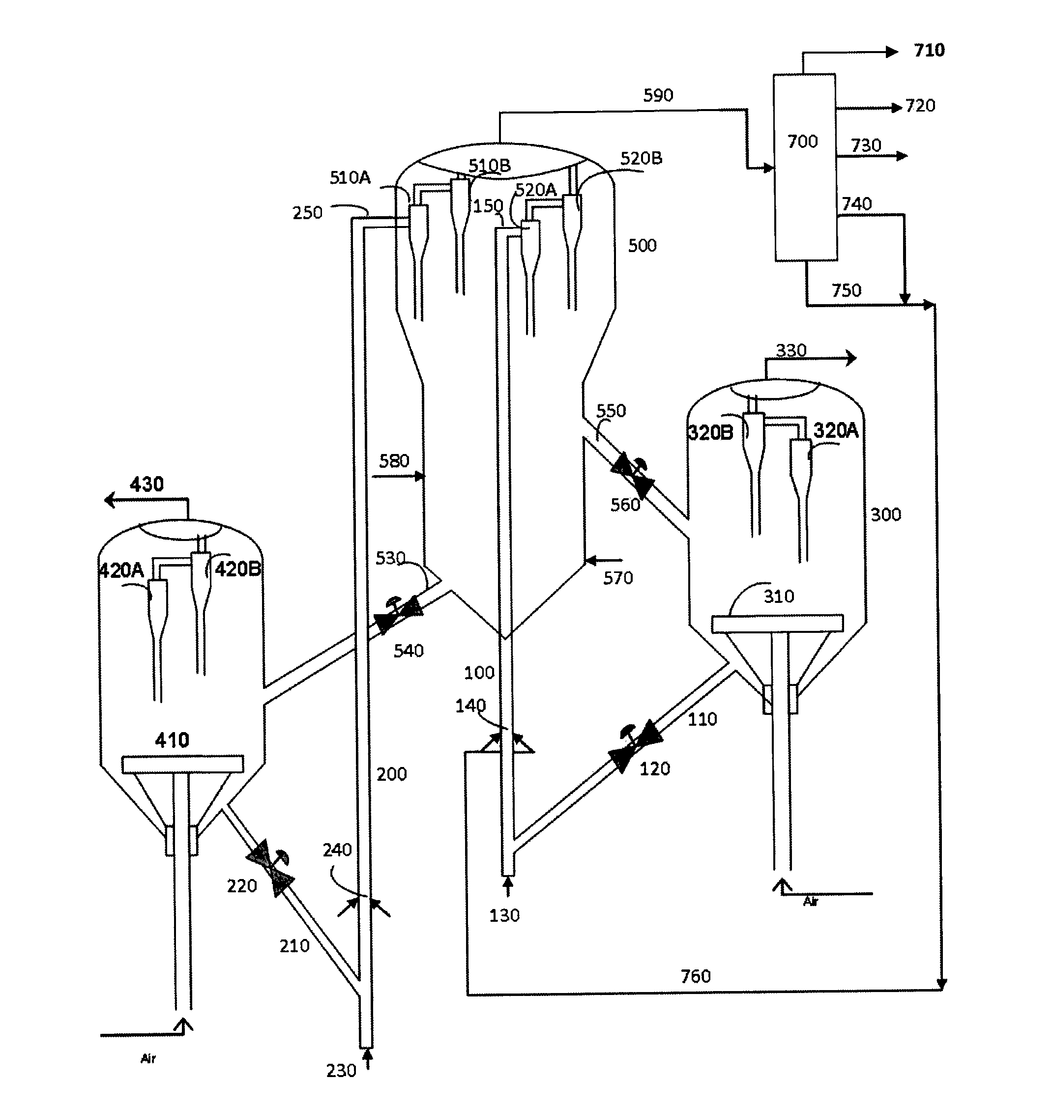
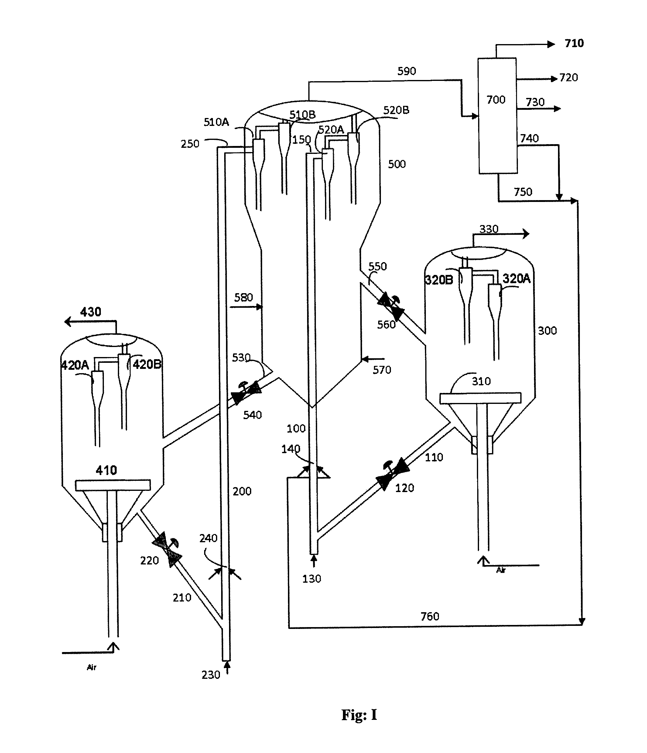
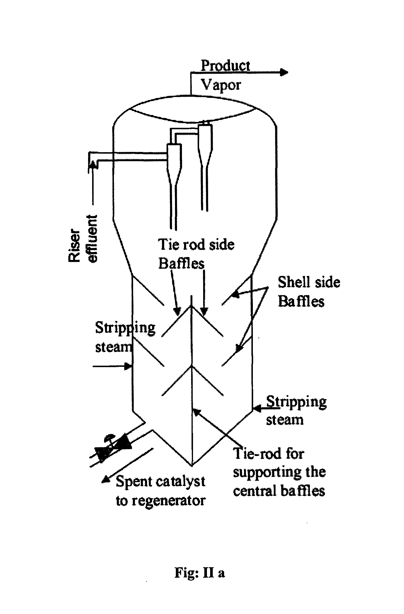
[0025]According to this invention there is provided a continuous fluidized catalytic cracking (FCC) process for converting a hydrocarbon feedstock containing higher concentrations of impurities such as Conradson Carbon Residue (CCR), metallic and other impurities such as herein described, into lighter hydrocarbon products by employing multiple elongated riser reactors, a common stripper cum separator, common fractionator and multiple regenerators for regenerating adsorbent and catalyst used therein concurrently comprising the following steps:[0026]a) Contacting the feedstock with hot adsorbent supplied from the adsorbent regenerator in the first riser reactor, the adsorbent being lifted to the feedstock injection zone using lifting medium, where the feedstock gets vaporized, purified and undergoes mild cracking to obtain substantially impurities free hydrocarbons vaporous products comprising mainly heavy cycle oil and materials higher boiling than said heavy cycle oil with minor amo...


PUM

PropertyMeasurementUnit
particle densityaaaaaaaaaa
particle sizeaaaaaaaaaa

Abstract

This invention provides a fluidized catalytic cracking apparatus and process for converting a hydrocarbon feedstock containing higher concentrations of Conradson Carbon Residue (CCR), metal impurities, etc into lighter products by employing two riser reactors in which the feed impurities are removed using an adsorbent in a first riser reactor and cracking a portion of first riser reactor liquid product in a second riser reactor to lighter products using the active catalyst thus eliminating the catalyst deactivation due to metal, impurities and FCC catalyst activity dilution effect to achieve a better conversion and higher catalyst longevity.

Description

FIELD OF THE INVENTION[0001]The present invention relates to a fluidized catalytic cracking (FCC) apparatus for resid upgradation. More particularly, the present invention further relates to a resid catalytic cracking process using adsorbent and catalyst regenerators, a common stripper cum separator vessel for continuous conversion of residual oil containing high concentration of Conradson Carbon Residue (CCR), poisonous metals such as vanadium, nickel, sodium, basic nitrogen and sulphur compounds impurities into lighter products using an adsorbent in a first riser reactor and catalyst in a second riser reactor for cracking of a portion of first riser reactor liquid product to lighter products thus eliminating the catalyst deactivation due to metal, impurities and FCC catalyst activity dilution effect to achieve a better conversion and higher catalyst longevity.BACKGROUND OF THE INVENTION AND PRIOR ART[0002]The present invention relates to Fluid Catalytic Cracking (FCC). It disclose...

Claims


Application Information

Patent Timeline
Patent Type & Authority Applications(United States)
IPC IPC(8): C10G51/02
CPCB01J8/0055C10G2300/4081B01J8/26B01J8/32B01J2208/0084C10G11/18C10G11/182C10G25/09C10G25/12C10G51/026C10G55/06C10G55/08C10G70/041C10G51/02C10G2300/4093C10G2300/708C10G2400/02C10G2400/20C10G2300/807C10G2300/205C10G2300/206C10G2300/305B01J8/1863
Inventor SAIDULU, G.BHUYAN, M.K.PRASAD, T.H.V.D.BHATTACHARYYA, DEBASISRAJAGOPAL, S.
Owner INDIAN OIL CORPORATION
Why Eureka
Try Eureka