
Steel rail for high speed and quasi-high speed railways and method of manufacturing the same

a high-speed, quasi-high-speed technology, applied in the direction of furnaces, heat treatment devices, roads, etc., can solve the problems of reducing the service life of the railway, affecting the safety of the running of the train, and affecting the smoothness of the rolling contact, so as to achieve excellent rolling contact fatigue properties

Inactive Publication Date: 2013-08-01
PANZHIHUA IRON AND STEEL +1
View PDF3 Cites 8 Cited by
  • Summary
  • Abstract
  • Description
  • Claims
  • Application Information

AI Technical Summary

Benefits of technology

The present invention provides a solution to the problems in the prior art by improving the rolling contact fatigue property of a steel rail for high speed or quasi-high speed railway use. This is achieved by reducing the carbon content in the steel rail and controlling cooling after rolling, which improves toughness, plasticity, and yield strength of the steel rail without compromising its strength and hardness levels. The energy value required for initiating and expanding microcracks formed at the surface of the steel rail due to fatigue is increased, resulting in improved rolling contact fatigue property and better service lifetime and transportation safety of the steel rail.

Problems solved by technology

However, practical application shows that a crack which has already been generated in an upper or side surface of a head portion of a steel rail is difficult to be worn away due to a relatively light axle load of generally 11-14 tons of a high speed train and little wear-out between wheel and rail in the practical operation, and under repeated wheel-rail contact force, propagation of the crack may be in turn aggravated, resulting in tendency of fracture of the steel rail, which seriously endangers running safety of the train.
On the other hand, if a wear rate of the steel rail is improved by a method of only decreasing strength and hardness of the steel rail, a plastic flow may occur in a surface of the steel rail to cause deviation in cross-sectional dimension of the steel rail so that the train cannot run along the railway, and a service lifetime of the railway may be also shortened due to excessive wear-out of the steel rail.
Accordingly, as for the high speed or quasi-high speed railways, a balance is difficult to be made between wear-out and rolling contact fatigue of the hot-rolled steel rail having a dominant component of pearlite.
A first method is to periodically grind an upper end of the steel rail by using a railway-grinding train, but this method has a problem in that the railway-grinding train is expensive, and meanwhile, there is a high traffic density on the high speed and quasi-high speed railways so that no sufficient grinding time can be spared.
However, simply reducing hardness may result in plastic deformation occurring on an upper surface of the steel rail after running a period of time, frequently accompanied by damages such as crack and peeling, which also negatively effect the lifetime and transportation safety of the steel rail.
However, in theory, a steel rail having a bainite structure, especially a lower bainite structure, has a significantly improved toughness and plasticity and an advantage in running safety as compared with a pearlite-based steel rail having the same strength level, but in terms of wear-out and rolling contact fatigue properties, its theoretical values are not consistent with its practical values.
CN1074058C, in order to obtain an ideal bainite structure, a strict control process for the steel rail is required, a large amount of valuable elements need to be added, causing the manufacturing cost of the steel rail to be much higher than the existing pearlite-based series rail, and even if the performances of the steel rail manufactured are excellent, it will be difficult to be mass-manufactured and widely used.
Therefore, manufacture of the bainite steel rail and wide application thereof to the high speed or quasi-high speed railway are limited due to strict manufacturing process as well as addition of a quantity of valuable alloys, thus a high manufacturing cost equal to or more than twice of the existing pearlite steel rails.

Method used


Image

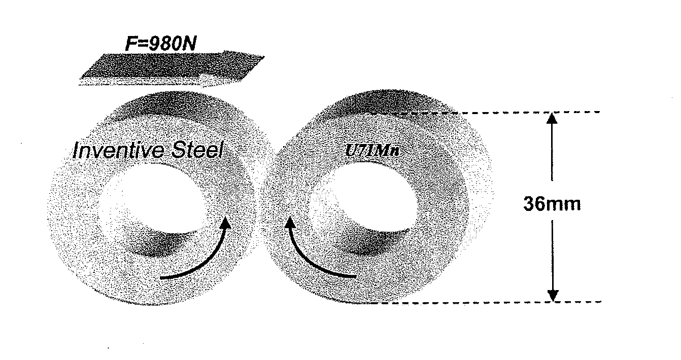
  • Steel rail for high speed and quasi-high speed railways and method of manufacturing the same
  • Steel rail for high speed and quasi-high speed railways and method of manufacturing the same
  • Steel rail for high speed and quasi-high speed railways and method of manufacturing the same

Examples


example 1

[0055]To obtain a steel rail having a composition as listed in Table 2 below, smelting by a converter, LF refining, vacuum degassing, continuous casting for billet, heating by a billet heating furnace, and rail rolling were sequentially performed, wherein the steel rail was rolled at a finishing rolling temperature of 903° C. and then was placed for 40 seconds; after that, when a temperature of a top surface of a rail head portion decreased to 800° C., compressed air began to be blown so as to uniformly cool the rail head portion at a cooling rate of 3.1° C. / s; and when the temperature of the top surface of the rail head portion reached 520° C., and temperatures of a rail waist and a rail base were respectively greater than 600° C. after blowing, the steel rail was placed in the air to be naturally cooled to a room temperature, thereby obtaining Sample 1.

example 2

[0056]Except for steps of controlled cooling after rolling, a steel rail was manufactured by using the same method as that in Example 1. Specifically, in this example, the steel rail was rolled at a finishing rolling temperature of 910° C. and then was placed for 45 seconds; after that, when a temperature of a top surface of a rail head portion decreased to 780° C., compressed air and a mixture of oil and air began to be blown so as to uniformly cool the rail head portion at a cooling rate of 2.9° C. / s; and when the temperature of the top surface of the rail head portion reached 514° C., and temperatures of a rail waist and a rail base were respectively greater than 600° C. after blowing, the steel rail was placed in the air to be naturally cooled to a room temperature, thereby obtaining Sample 2.

example 3

[0057]Except for steps of controlled cooling after rolling, a steel rail was manufactured by using the same method as that in Example 1. Specifically, in this example, the steel rail was rolled at a finishing rolling temperature of 900° C. and then was placed for 42 seconds; after that, when a temperature of a top surface of a rail head portion decreased to 770° C., a mixture of oil and air began to be blown so as to uniformly cool the rail head portion at a cooling rate of 2.7° C. / s; and when the temperature of the top surface of the rail head portion reached to 530° C., and temperatures of a rail waist and a rail base were respectively greater than 600° C. after blowing, the steel rail was placed in the air to be naturally cooled to a room temperature, thereby obtaining Sample 3.


PUM

PropertyMeasurementUnit
temperatureaaaaaaaaaa
tensile strengthaaaaaaaaaa

Abstract

The present discloses a steel rail for high speed and quasi-high speed railways and a manufacturing method thereof. The steel rail having a superior rolling contact fatigue property can be obtained by reducing content of carbon in conjunction with controlled cooling after rolling. The steel rail includes 0.40-0.64% by weight of C, 0.10-1.00% by weight of Si, 0.30-1.50% by weight of Mn, less than or equal to 0.025% by weight of P, less than or equal to 0.025% by weight of S, less than or equal to 0.005% by weight of Al, more than 0 and less than or equal to 0.05% by weight of a rare earth element, more than 0 and less than or equal to 0.20% by weight of at least one of V, Cr, and Ti, and a remainder of Fe and inevitable impurities. The steel rail manufactured according to the method of the present invention maintains the strength and hardness of the existing steel rail for the high speed railways, while enhancing the toughness, plasticity and yield strength, and an energy value required for initiating and expanding microcracks formed at the surface of the steel rail due to fatigue is increased, and thus under the same conditions, the rolling contact fatigue property of the steel rail can be improved, thereby finally improving the service lifetime and the transportation safety of the steel rail.

Description

FIELD OF THE INVENTION[0001]The present invention relates to a steel rail material, more particularly, a steel rail adapted to be used in a high speed or quasi-high speed railway and a method of manufacturing the same.DESCRIPTION OF RELATED ART[0002]There have been three main kinds of railways nowadays in the world, i.e., heavy haul railway, high speed railway, and mixed passenger and freight railway. As for steel rails for the heavy haul railway, because of generally 25 t-40 t of an axle load of a train, great contact stress between wheel and rail, and harsh forces, a carbon steel or alloy steel rail having more than 0.75% of C, a tensile strength of 1200 MPa or more, and a full pearlite structure is generally used to ensure that the steel rail has excellent resistance to wear. As for the high speed railway, since it is mainly used in passenger transport and the train has a light axle load, steel rails for the high speed railway are generally required to have an excellent antifatig...

Claims


Application Information

Patent Timeline
Patent Type & Authority Applications(United States)
IPC IPC(8): E01B5/02
CPCC21D9/04C21D2211/005C21D2211/009Y10T29/49991C22C38/14C22C38/18E01B5/02C22C38/12C22C38/005C22C38/02C22C38/04C22C38/06C22C38/24C22C38/28
Inventor MEI, DONGSHENGZOU, MINGHAN, ZHENYUXU, QUANGUO, HUADENG, YONGLI, DADONGTANG, LIZHAO, YUNLIU, JIANHUA
Owner PANZHIHUA IRON AND STEEL
Learn More