Sweep-Based Membrane Gas Separation Integrated With Gas-Fired Power Production And CO2 Recovery

a gas separation and membrane technology, applied in the direction of indirect carbon-dioxide mitigation, machines/engines, electric generator control, etc., can solve the problems of difficult and expensive recovery of carbon dioxide from this dilute gas stream, difficult and difficult to treat, and high temperature of the gas entering the turbine, so as to reduce the environmental impact of the plant

Active Publication Date: 2013-08-08
MEMBRANE TECH & RES
View PDF38 Cites 23 Cited by
  • Summary
  • Abstract
  • Description
  • Claims
  • Application Information

AI Technical Summary

Benefits of technology

[0042]It is the great enrichment of carbon dioxide in the incoming air or oxygen stream brought about by step (e) that enables this composition-adjusted air stream to be tapped as the source stream for carbon dioxide removal and capture for the overall process. Prior art power plants that do not make use of a sweep-based membrane separation step are only able to remove carbon dioxide from the post-combustion or post-turbine exhaust gas, and therefore cannot take advantage of the combined benefits of low volume, high concentration, high pressure, and modest temperature mentioned above.
[0043]The residue stream withdrawn per step (e)(iv) forms the treated flue gas produced by the process, and is usually discharged to the environment via the power plant stack. The carbon dioxide content is preferably less than about 2 vol %; more preferably less than about 1 vol %, and most preferably no greater than about 0.5 vol %. The reduction of the carbon dioxide content to 20%, 10%, or less of the conventional content of flue gas from a gas-fired power plant greatly reduces the environmental impact of the plant.

Problems solved by technology

Many combustion processes produce flue gas emissions contaminated with carbon dioxide that contribute to global warming and environmental damage.
Gas-fired power plants are an important source of such flue gases, and their emissions are particularly challenging to treat because the volume of flue gas generated is very large and the carbon dioxide concentration, is low.
A major plant design issue is the temperature of the gas entering the turbines.
Recovery of carbon dioxide from this dilute, low-pressure, yet very high-volume gas stream is, difficult and very expensive.
Combined cycle power generation is inherently more expensive than using a gas-turbine-only process, because additional equipment is required.

Method used


Image

  • Sweep-Based Membrane Gas Separation Integrated With Gas-Fired Power Production And CO2 Recovery
  • Sweep-Based Membrane Gas Separation Integrated With Gas-Fired Power Production And CO2 Recovery
  • Sweep-Based Membrane Gas Separation Integrated With Gas-Fired Power Production And CO2 Recovery

Examples


example 1

Polymeric Membrane Permeation Experiments

[0108]Sets of representative permeation experiments were performed with two different composite membranes, each having a polyether-based selective layer. The properties of the membranes as measured with a set of pure gases at 6.7 bar absolute and 30° C. are shown in Tables 1 and 2.

TABLE 1GasPermeance (gpu)*CO2 / Gas SelectivityCarbon dioxide1,000  —Nitrogen2050Oxygen4025Methane5020Water>2,000**  —*Gas permeation unit; 1 gpu = 1 × 10⁻⁶ cm3(STP) / cm2 · s · cmHg**Estimated, not measured

TABLE 2GasPermeance (gpu)*CO2 / Gas SelectivityCarbon dioxide1,000  —Nitrogen3033Oxygen6017Hydrogen100 10Water5,000** —*Gas permeation unit; 1 gpu = 1 × 10⁻⁶ cm3(STP) / cm2 · s · cmHg**Estimated, not measured

example 2

Molten Salt Membranes Used for Gas Separation Step

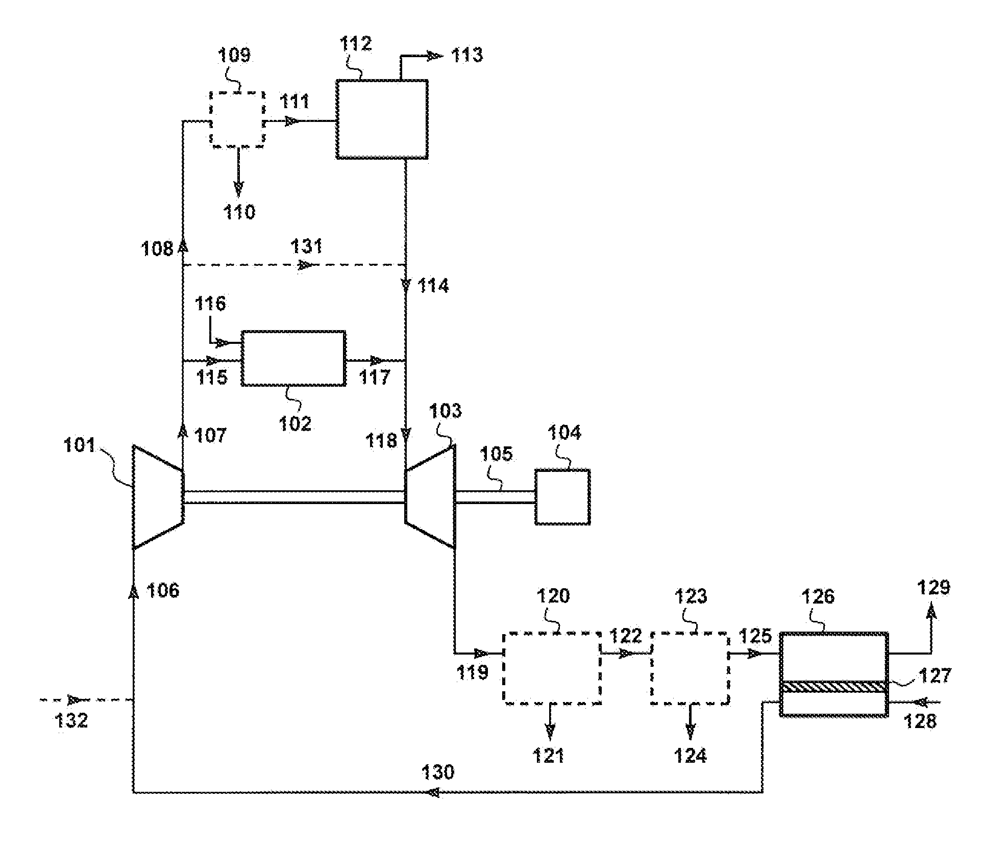
[0109]A calculation was performed to model the performance of the process of the invention in accordance with the design shown in FIG. 1. The process was assumed to use natural gas as fuel, and to include an HRSG. The fuel and air streams were sized to be consistent with a typical plant producing 500 MWe of power,

[0110]The sweep-based membrane separation step 126 was assumed to be carried out using polymeric membranes having a carbon dioxide / nitrogen selectivity of 50 and carbon dioxide / oxygen selectivity of 25. The membranes were assumed to be optimized to give a carbon dioxide permeance of 5,000 gpu.

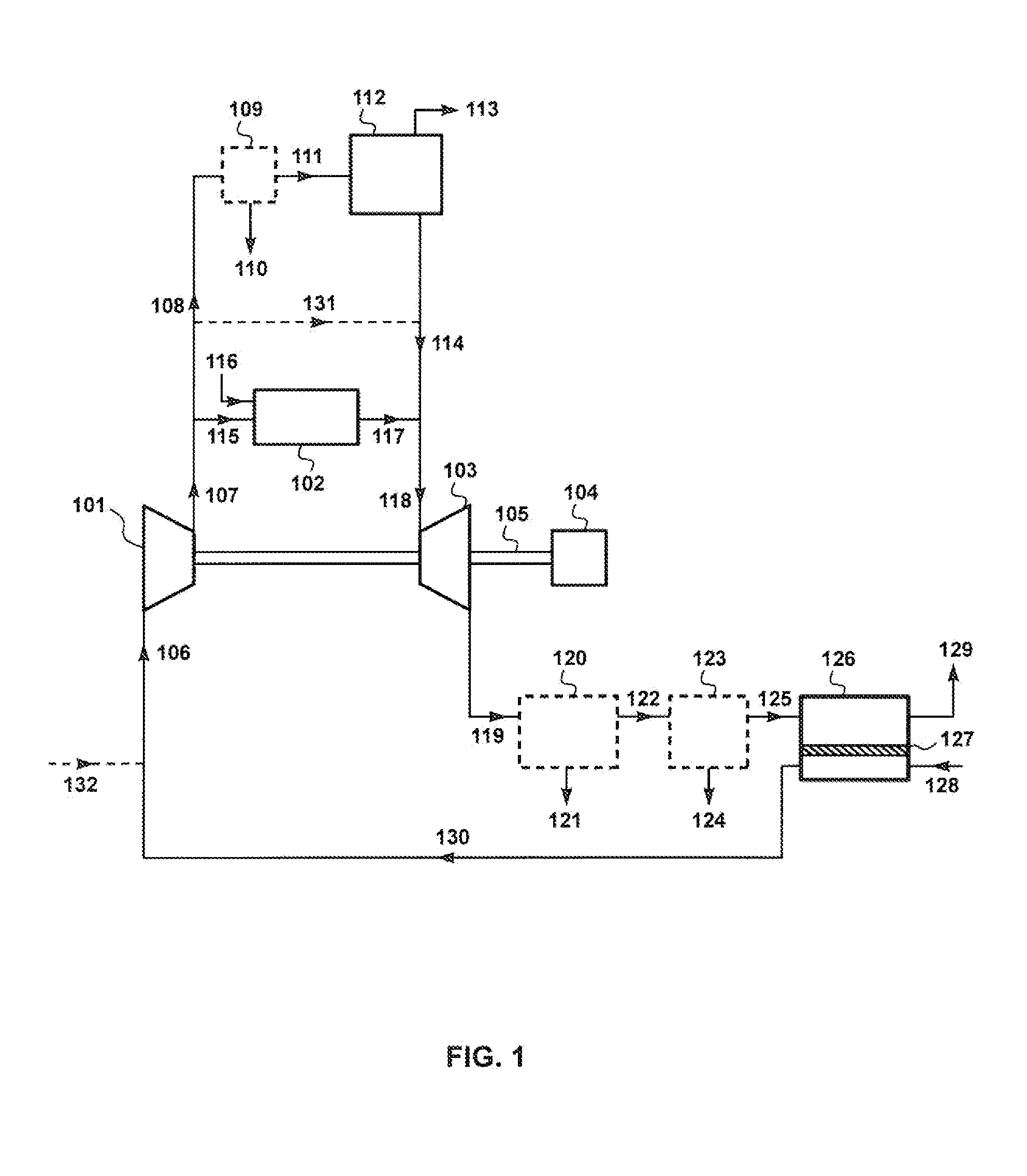
[0111]The permeate / sweep air stream was assumed to be compressed to 30 bar, and then split in a 70:30 ratio, with 70% being sent as stream 115 to the combustor and 30% being directed as stream 108 to the carbon dioxide removal step, 112.

[0112]Step 112 was assumed to be carried out using molten salt membranes operating at a temperature o...

example 3

Molten Salt Membranes Used for Gas Separation Step, Permeate Pressure at 2 Bara

[0114]The calculation of Example 2 was repeated, except this time it was assumed that the permeate side of the molten salt membranes was maintained at 2 bara. The results of the calculations are shown in Table 4.

TABLE 4Stream / numberFeed toFeed toSweepCompressorcapturecombustionTurbineMembraneCO2MembraneFuelgasfeedstepstepexhaustfeedpermeateresidue116128106108115119125113129Molar4,38076,587104,60032,02773,220104,82295,6244,93267,610flow(kmol / h)Temp381525523536655255237(° C.)Pressure301130301221(Bara)Component Vol %Oxygen020.715.015.015.16.47.13.010.2Nitrogen1.677.360.660.360.660.566.36.287.6Carbon1.0022.022.221.822.224.391.00.7dioxideMethane93.100000000Water01.01.81.81.810.21.500.5Argon01.00.70.70.70.70.801.0Ethane3.200000000Propane0.700000000n-butane0.400000000

[0115]In this case, the concentration of the carbon dioxide product stream, 113, is 91 vol %, slightly lower than in the previous example. However,...


PUM

PropertyMeasurementUnit
atmospheric pressureaaaaaaaaaa
temperatureaaaaaaaaaa

Abstract

A process involving membrane-based gas separation and power generation, specifically for controlling carbon dioxide emissions from gas-fired power plants. The process includes a compression step, a combustion step, and an expansion/electricity generation step, as in traditional power plants. The process also includes a sweep-driven membrane separation step and a carbon dioxide removal or capture step. The carbon dioxide removal step is carried out on a portion of gas from the compression step.

Description

[0001]The present application is a continuation-in-part and claims the benefit of U.S. application Ser. No. 13 / 665,620, filed Oct. 31, 2012; which is a continuation-in-part and claims the benefit of U.S. application Ser. No. 13 / 548,827, filed Jul. 13, 2012; which is a continuation-in-part and claims the benefit of U.S. application Ser. No. 13 / 115,726, filed May 25, 2011, which issued Jul. 17, 2012, as U.S. Pat. No. 8,220,248; which is a continuation-in-part and claims the benefit of U.S. application Ser. No. 13 / 122,136, filed Mar. 31, 2011, which issued May 15, 2012, as U.S. Pat. No. 8,177,885; which is a national stage application of, and claims the benefit of, PCT Application No. PCT / US10 / 02480, filed Sep. 13, 2010, the entire contents of all of which applications are hereby incorporated by reference.FIELD OF THE INVENTION[0002]The invention relates to membrane-based gas separation processes, and specifically to processes using a sweep gas on the permeate side of the membrane to r...

Claims


Application Information

Patent Timeline
Patent Type & Authority Applications(United States)
IPC IPC(8): F02C7/00H02K7/18
CPCB01D53/1475Y02E20/344B01D2251/606B01D2252/10B01D2252/20478Y02C10/04Y02C10/10B01D53/22B01D53/62F02C3/34F23C9/00B01D2256/22F02C7/00H02K7/1823B01D2257/102B01D2257/104B01D2257/504B01D2258/0283F23L2900/07001Y02E20/16Y02E20/18Y02E20/322F23J15/02F23L7/007F23J2215/50B01D2251/306Y02A50/20Y02C20/40Y02E20/32Y02E20/34
Inventor WEI, XIAOTONGBAKER, RICHARD WMERKEL, TIMOTHY CFREEMAN, BRICE C.
Owner MEMBRANE TECH & RES
Why Eureka
Try Eureka