Electric vehicle

Inactive Publication Date: 2013-08-29
OBSCHESTVO S OGRANICHENNOY OTVETSTVENNOSTYU TOVARISCHESTVO ENERGETICHESKIKH I ELEKTROMOBILNIKH PROEKTOV
View PDF1 Cites 9 Cited by
  • Summary
  • Abstract
  • Description
  • Claims
  • Application Information

AI Technical Summary

Benefits of technology

[0016]It is an object of the present invention to eliminate some of the aforesaid disadvantages of the prior art apparatuses and thus to increase the factor of utilization of energy recovered in braking, reducing the EV weight and space saving paramete

Problems solved by technology

Disadvantage of the prior art apparatus consists in high power-to-size ratio of the power unit due to overvoltage of the power supply when the storage battery is connected in series to the capacitor bank, and high complexity of the apparatus owing to the use of an additional battery charging unit.
Disadvantage of the prior art apparatus consists in the presence of an isolation diode between the main power source, i.e. the storage battery, and the main user, which is a converter with an electric drive motor, which causes additional losses through the diode, basically in the motor conditions, and the presence of the heat sink of the isolation diode, installed in the power circuit, worsens weight and space saving parameters of the electric vehicle.
This imposes additional requirements when selecting the elements of the power amplifier of the converter, namely, the power transistors, capacitors of the power filters, drivers and the like, which, as a rule, leads to over-estimation of power-to-size rat

Method used


Image

  • Electric vehicle
  • Electric vehicle
  • Electric vehicle

Examples


Embodiment Construction

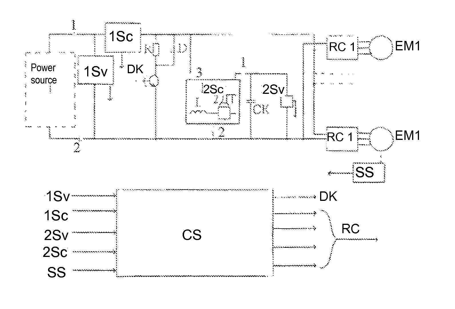
[0034]FIG. 1 shows a schematic circuit of the proposed EV comprising a self-contained (on-board) or coupled with an external reversible power source with terminals 1 and 2 at which the voltage is measured by a voltage sensor, and the current is measured by a current sensor.

[0035]Terminals 1 and 2 are used to connect in series a ballast resistor R (parallel-connected to a bypass diode (D)), a discharge key (DK) and reversible converters (RC1 to RCi) providing for regulation of aped and / or torque of electric motors (EM1 to EMi) coupled to the EV wheels via a mechanical transmission or without a transmission (motor-wheels) (not shown in the schematic).

[0036]The schematic also represents a supercapacitor (SC) which voltage is measured by sensor 2Sv. SC is connected to the output terminals of the reversible converter (RC) 4 and 2 the output terminals 3 and 2 of which are connected to terminals 1 and 2 of power source 1.

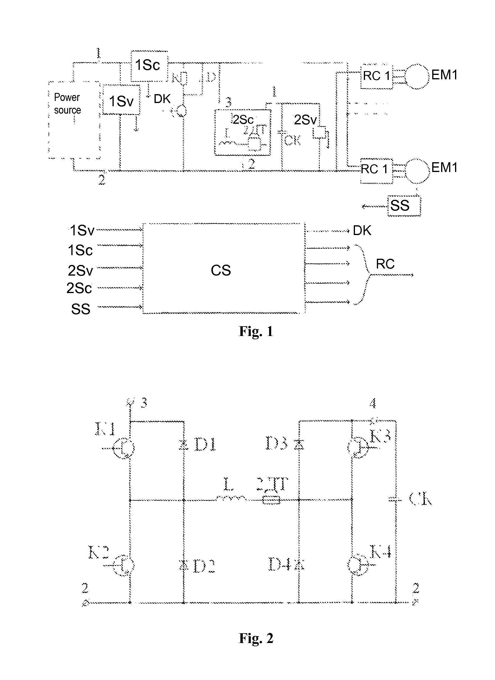
[0037]FIG. 2 illustrates an embodiment of a reversible converter (RC)...


PUM


Abstract

An electric vehicle is proposed which comprises a reversible power supply (or which is coupled with a reversible power supply), one or more electric motors that are connected to wheels via a mechanical transmission (or without such transmission), one or several reversible converters, which make it possible to control the speed and/or torque of the aforesaid electric motors in all four quadrants of electromechanical characteristic, a high capacity capacitor (supercapacitor) and a ballast resistor.
The vehicle is provided with a reversible dc step-up/step-down transformer, two current sensors, two voltage sensors, a vehicle speed sensor, a speed sensor for one of the electric motors and a control system, wherein one or several reversible converters are connected directly to the terminals of the reversible power supply. The supercapacitor is connected to the terminals via the reversible transformer. The ballast resistor, parallel-connected to a bypass diode, is connected in series with a discharge key to the same terminals. One sensor indicates the current value and direction of the reversible power supply, the second sensor takes measurements of coil (inductance choke) current being a component of the transformer. One voltage sensor measures the voltage at the capacitor terminals. The outputs of the aforesaid sensors, together with the output of the speed sensor, are connected to the inputs of the control system, the outputs of which are connected to the control inputs of the transformer and a discharge key. The technical result is a reduction in energy loss as a result of the increased use of recovered energy.

Description

TECHNICAL FIELD[0001]The present invention relates to the field of electric vehicles (EVs) and can be used both on the EVs equipped with self-contained power supply and on the EVs connected to the external power supply (in trams, trolleybus, metropolitan trains).[0002]In more detail, this invention relates to the technical decisions on recovery (storage) of electric energy in the course of the transport vehicle braking.BACKGROUND ART[0003]There are already known various decisions for improvement of recovered power usage effectiveness in the process of an electric vehicle braking.[0004]For example, there is known a “Battery-fed vehicle traction motor with capacitor boost” (Patent FR 2757806 A1, B60L 11 / 00, dated Mar. 7, 1998). The apparatus comprises a motor that is connected to wheels of an electric vehicle with electronic control powered from a storage battery, a capacitor bank and a logic unit. The logic unit output is connected to a relay coil the contacts of which connect the ca...

Claims


Application Information

Patent Timeline
IPC IPC(8): B60L11/18B60L50/15
CPCB60L3/108B60L11/1862B60L11/005B60L11/1805B60L2210/12B60L2210/14B60L2220/42B60L2240/12B60L2240/421B60L2240/423B60L2240/547Y02T10/646Y02T10/7005Y02T10/7022Y02T10/7225Y02T10/7233Y02T10/92Y02T10/648B60L7/16B60L50/40B60L50/52B60L58/13Y02T10/64Y02T10/70Y02T10/72Y02T10/7072Y02T90/14B60L53/20B60L50/15B60L15/20
Inventor VERSHININ, DMITRIY VENIAMINOVICHDASHKO, OLEG GRIGORIEVICHSMOTROV, EVGENY ALEXANDROVICHZENIN, SERGEY BORISOVICHDOLGOLAPTEV, ANATOLIY VASILYEVICH
Owner OBSCHESTVO S OGRANICHENNOY OTVETSTVENNOSTYU TOVARISCHESTVO ENERGETICHESKIKH I ELEKTROMOBILNIKH PROEKTOV
Why Eureka
Try Eureka