System for substance separation and energy recovery by thermal treatment

a technology of energy recovery and substance separation, applied in the direction of sludge treatment by oxidation, furnaces, combustion types, etc., can solve the problems of difficult recovery of latent steam heat, incomplete combustion and air pollutants, and low combustion temperature and air pollutants

Active Publication Date: 2013-09-05
TAIWAN CLEAN ENERGY TECH
View PDF6 Cites 11 Cited by
  • Summary
  • Abstract
  • Description
  • Claims
  • Application Information

AI Technical Summary

Benefits of technology

[0012]The substance to be thermally treated is fed into the thermal treatment reactor, and a high-temperature gaseous heating medium is introduced into the reactor simultaneously. In the reactor, the substance to be treated increases its temperature through direct contact with the gaseous heating medium. The substance to be treated will generates a gaseous substance and a residual substance, wherein the gaseous substance is used as a heating medium and fed into the heat exchanger via a circulation fan through the circulation piping to be heated and then fed again into the thermal treatment reactor.
[0013]The substance in the thermal treatment reactor forms a gaseous substance and a residual substance because of being heated, wherein the gaseous substance has the same compositions as the high-temperature heating medium fed into the thermal treatment reactor; therefore, the gaseous substances within the circulation piping are increased in amount. The increased amount of gaseous substances is discharged through the discharge piping to prevent the pressure from rising continuously, and the gaseous substance is transmitted through the discharge piping to the latent heat recovering device, wherein the latent heat recovering device can be an indirect heat exchanger. Inside the latent heat recovering device, the gaseous substance condenses and releases latent heat for heating cold fluids; the gaseous substance thus forms a condensed substance and a non-condensed substance after passing through the latent heat recovering device. To sum up, the substances are separated into a residual substance and a gaseous substance through thermal treatment, wherein the gaseous substance is condensed to form a condensed substance and a non-condensed substance by the latent heat recovering device, thereby achieving the objective of substance separation.
[0014]The residual substance can be a product. While the residual substance used as a fuel, it can be fed into proper equipments such as a boiler or a gasifier. In a gasifier, the residual will be gasified to syngas. The combustible syngas is then mixed with combustion air via a gas burner to complete combustion in the combustion furnace. The generated high-temperature flue gas is then used as a heat source to heat up the circulating heating media via a indirect heat exchanger. In the heat exchanger, the flue gas exchanges heat to the heating media. The heating media is then fed into the thermal treatment reactor. The remaining sensible heat of the flue gas can be recovered by other heat recovering devices, such as a boiler or an air pre-heater.

Problems solved by technology

During combustion, these low calorific value substances results in low combustion temperature and air pollutants due to incomplete combustion.
The conventional utilization of the high moisture content and low calorific value substance as fuel has the following disadvantages: first of all, energy recovery of high moisture content substances through a direct combustion process results in incomplete combustion and air pollutants.
Therefore, the latent heat of the steam is very difficult to recover.
However, the hot air (heating media) containing incondensable gases results in low dew point of the air-steam mixture.
Therefore, the latent heat absorbed by water during drying is also hard to recover.
Another disadvantage of conventional hot air drying is the substance to be dried will be oxidized and even catch fire due to the existing of oxygen.
Furthermore, conventional hot air drying will produce large amount of pollutants such as dioxins and odors.

Method used


Image

  • System for substance separation and energy recovery by thermal treatment
  • System for substance separation and energy recovery by thermal treatment
  • System for substance separation and energy recovery by thermal treatment

Examples


Embodiment Construction

[0016]In order to give the examiners a better understanding of the technical scheme of the present invention, a preferred embodiment is illustrated as below.

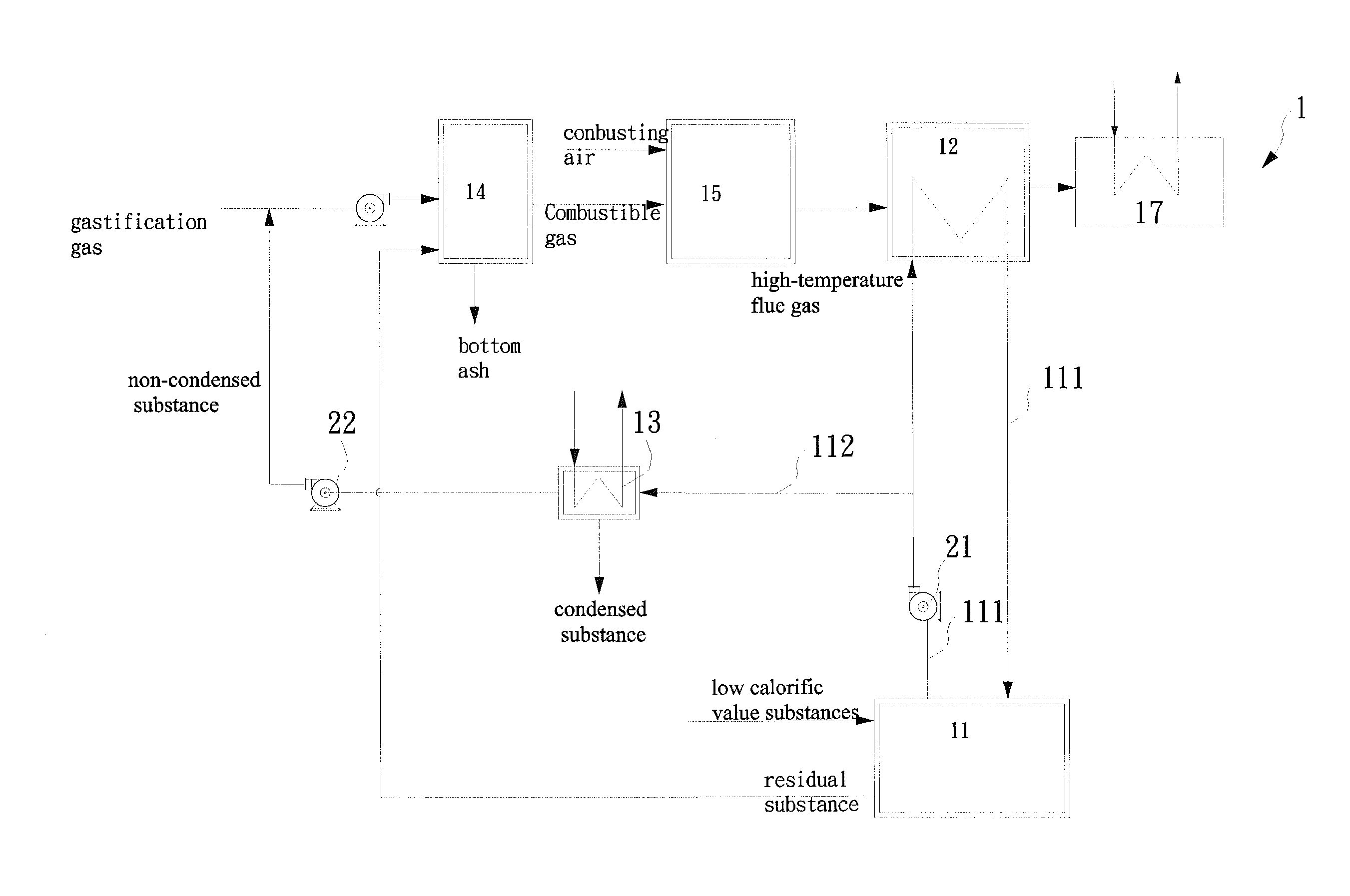
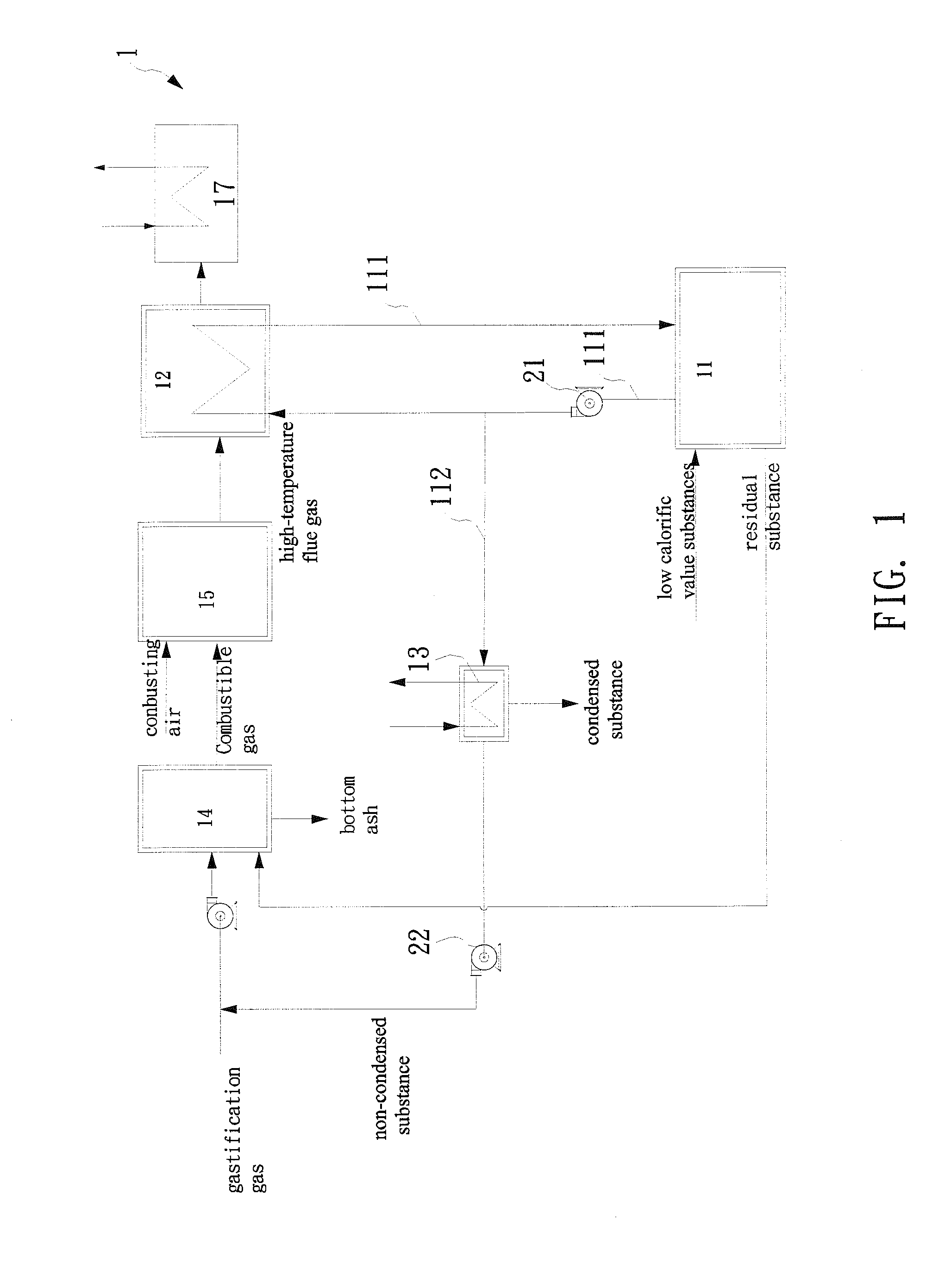
[0017]Please refer to FIG. 1; the substance separation and energy recovery system 1 of the present invention includes a thermal treatment reactor 11, a circulation piping 111, a heat exchanger 12, a discharge piping 112, a latent heat recovering device 13, a gasifier 14, and a combustion furnace 15.

[0018]First of all, the low calorific value substance is fed into the thermal treatment reactor 11. The low calorific value substance can be, such as sludge, of which the moisture content is as high as 60-80%, with a better level of humidity being 60%. The thermal treatment reactor 11 (for example, a rotary drum dryer) is used for thermal treatment such as drying, pyrolysis, or torrefaction of the low calorific value material. In the embodiment of sludge, the thermal treatment is drying. The following description uses sludge as an exa...


PUM


Abstract

A system for substance separation and energy recovery by thermal treatment is disclosed. The system includes a thermal treatment reactor, a circulation piping, a heat exchanger, a discharge pipeline, a latent heat recovering device, a gasifier, and a combustion furnace. The substance is fed into the thermal treatment reactor for heating the treated substance so as to produces a gaseous substance by evaporation or pyrolysis. The treated substance is separated into the gaseous substance circulating between the heat exchanger and the thermal treatment reactor and a residual substance being fed into the thermal treatment reactor. The increased gaseous substance, during the circulation process, is fed into a latent heat recovery device, wherein the gaseous substance exchanges heat with a cold fluid and condenses to release latent heat, forming a liquid condensed substance and a non-condensed substance.

Description

BACKGROUND OF THE INVENTION[0001]1. Field of the Invention[0002]The present invention relates to a system for a substance separation and energy recovery by thermal treatment; and more particularly, to an energy recovery system used to process low calorific value substances.[0003]2. Description of the Related Art[0004]Most substances with high moisture content have low calorific value. During combustion, these low calorific value substances results in low combustion temperature and air pollutants due to incomplete combustion.[0005]Therefore, most high moisture content substances usually will be dried to remove water and increase heating value (as in the cases of coal drying or sludge drying) prior to combustion. A substance with lower moisture content helps to achieve a higher combustion temperature and better combustion stability.[0006]The most popular drying method is hot air drying. Air is heated to a relative high temperature and is introduced to contact with the substances to be...

Claims


Application Information

Patent Timeline
Patent Type & Authority Applications(United States)
IPC IPC(8): F27D17/00
CPCF27D17/004C02F11/12F23G5/027F23G5/46F23G7/001C10J2300/0909C10J2300/0956C10J2300/1606C10J2300/1687C10J2300/1823C10J2300/1876F23G2201/303F23G2201/40F23G2206/10C10J3/00C10J2300/0923C02F11/06C02F11/10C10K1/02C02F11/13Y02W10/30Y02W10/40Y02P20/10
Inventor GER, JIA-SHYAN
Owner TAIWAN CLEAN ENERGY TECH
Why Eureka
Try Eureka