Multiple Frequency Sputtering for Enhancement in Deposition Rate and Growth Kinetics of Dielectric Materials

a dielectric material and multi-frequency sputtering technology, applied in the direction of electrolysis components, vacuum evaporation coatings, coatings, etc., can solve the problems of low deposition rate, limited sputtering process, low thermal conductivity of dielectric materials, etc., to improve the deposition rate and improve the quality of thin films , improve the effect of sputtering ra

Inactive Publication Date: 2013-09-26
APPLIED MATERIALS INC
View PDF7 Cites 13 Cited by
  • Summary
  • Abstract
  • Description
  • Claims
  • Application Information

AI Technical Summary

Benefits of technology

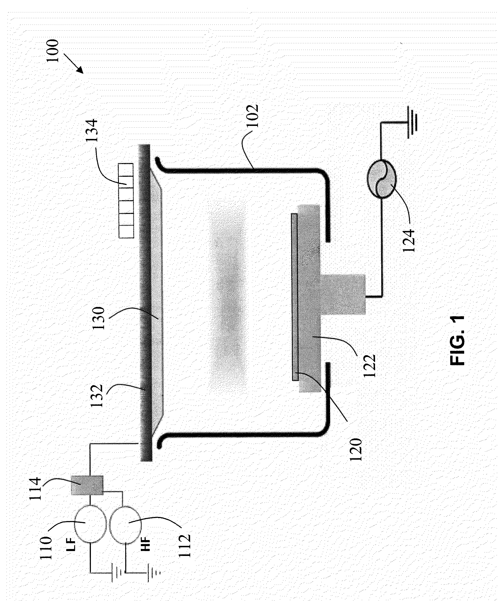
[0005]The present invention relates, in general, to systems and methods for improving deposition of dielectric thin films which include the use of dual frequency target power sources for improved sputtering rates, improved thin film quality and reduced thermal stress in the target. The dual RF frequencies provide independent control of plasma ion density and ion energies, by using, respectively, higher frequency and lower frequency RF target power sources. The present invention is generally applicable to PVD sputter deposition tools for dielectric materials. Specific examples are lithium containing elect...

Problems solved by technology

In addition, these dielectric materials typically have low thermal conductivity which limits the sputtering process at high frequency to lower power density regimes, in order to avoid problems such as thermal gradient induced stresses in the sputtering ta...

Method used


Image

  • Multiple Frequency Sputtering for Enhancement in Deposition Rate and Growth Kinetics of Dielectric Materials
  • Multiple Frequency Sputtering for Enhancement in Deposition Rate and Growth Kinetics of Dielectric Materials
  • Multiple Frequency Sputtering for Enhancement in Deposition Rate and Growth Kinetics of Dielectric Materials

Examples


Embodiment Construction

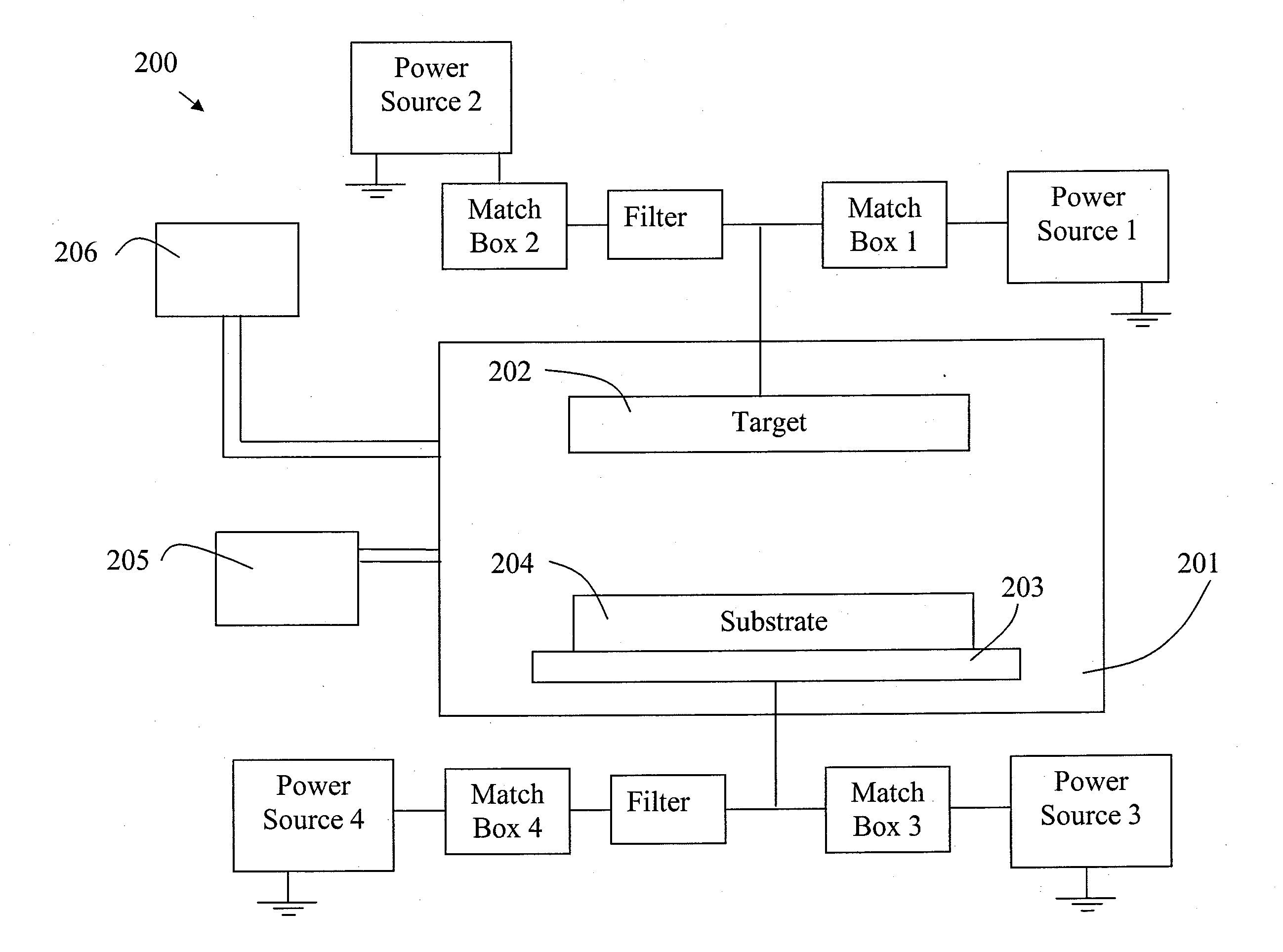
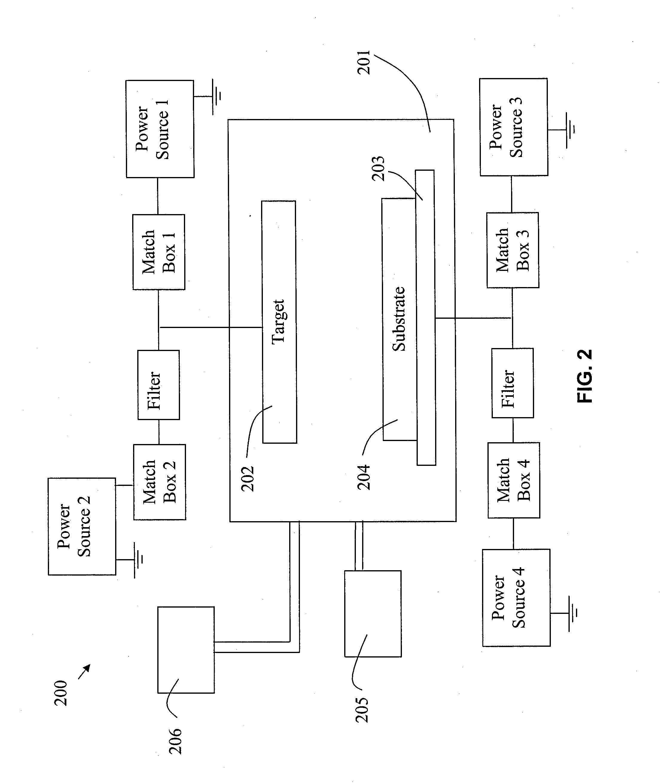
[0021]Embodiments of the present invention will now be described in detail with reference to the drawings, which are provided as illustrative examples of the invention so as to enable those skilled in the art to practice the invention. Notably, the figures and examples below are not meant to limit the scope of the present invention to a single embodiment, but other embodiments are possible by way of interchange of some or all of the described or illustrated elements. Moreover, where certain elements of the present invention can be partially or fully implemented using known components, only those portions of such known components that are necessary for an understanding of the present invention will be described, and detailed descriptions of other portions of such known components will be omitted so as not to obscure the invention. In the present specification, an embodiment showing a singular component should not be considered limiting; rather, the invention is intended to encompass ...


PUM

PropertyMeasurementUnit
Frequencyaaaaaaaaaa
Frequencyaaaaaaaaaa
Frequencyaaaaaaaaaa

Abstract

A method of sputter depositing dielectric thin films may comprise: providing a substrate on a substrate pedestal in a process chamber, the substrate being positioned facing a sputter target; simultaneously applying a first RF frequency from a first power supply and a second RF frequency from a second power supply to the sputter target; and forming a plasma in the process chamber between the substrate and the sputter target, for sputtering the target; wherein the first RF frequency is less than the second RF frequency, the first RF frequency is chosen to control the ion energy of the plasma and the second RF frequency is chosen to control the ion density of the plasma. The self-bias of surfaces within said process chamber may be selected; this is enabled by connecting a blocking capacitor between the substrate pedestal and ground.

Description

CROSS-REFERENCE TO RELATED APPLICATIONS[0001]This application claims the benefit of U.S. Provisional Application No. 61 / 533,074 filed Sep. 9, 2011, incorporated herein by reference in its entirety.FIELD OF THE INVENTION[0002]Embodiments of the present invention relate generally to equipment for dielectric thin film deposition and more specifically to sputtering equipment for dielectric thin films including multiple frequency power sources for the sputter target.BACKGROUND OF THE INVENTION[0003]Typically dielectric materials, such as Li3PO4 to form LiPON (lithium phosphorus oxynitride), primarily because of their very low electrical conductivity, require high frequency power supplies (RF) to enable (PVD) sputtering of dielectric targets for thin film deposition. In addition, these dielectric materials typically have low thermal conductivity which limits the sputtering process at high frequency to lower power density regimes, in order to avoid problems such as thermal gradient induced...

Claims


Application Information

Patent Timeline
IPC IPC(8): C23C14/34
CPCH01J37/3405C23C14/3471C23C14/345H01J37/32165C23C14/00H01L21/02631
Inventor JIANG, CHONGKWAK, BYUNG-SUNG LEOSTOWELL, MICHAELARMSTRONG, KARL
Owner APPLIED MATERIALS INC
Why Eureka
Try Eureka