Heat resistance layer for nonaqueous secondary battery, process for producing the same, and nonaqueous secondary battery

a secondary battery and heat resistance layer technology, applied in the field of nonaqueous electrochemical cells, can solve the problems of solvent penetration, low deposition rate, and high cost of ceramic coating application methods, and achieve the effect of increasing mechanical strength and compression resistance of the coated component and preventing the cell from short circui

Inactive Publication Date: 2013-10-17
ENMAT GLOBAL
View PDF2 Cites 31 Cited by
  • Summary
  • Abstract
  • Description
  • Claims
  • Application Information

AI Technical Summary

Benefits of technology

[0007]The present disclosure relates to a non-aqueous electrochemical cell having a heat-resistant coating on at least one of a negative electrode, a positive electrode, and a separator, if provided. The heat-resistant coating may consume heat in the cell to stabilize the cell, act as an electrical insulator to prevent the cell from short circuiting, and increase the mechanical strength and compression resistance of the coated component.

Problems solved by technology
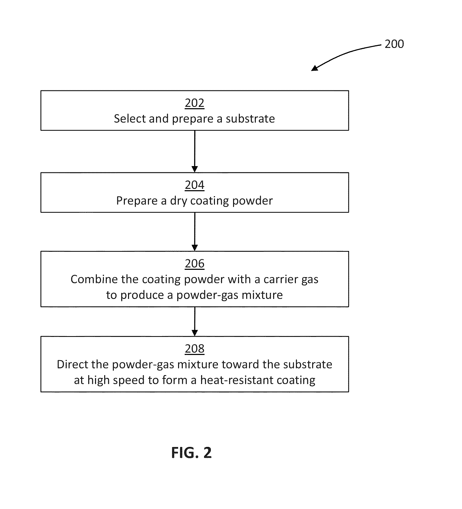
However, because it is thin, soft, and sensitive to deformation under force, the separator risks being pierced or otherwise damaged during the manufacturing process, which may cause the cell to short circuit.
However, known methods for applying such ceramic coatings, including chemical vapour deposition (CVD) methods and physical vapour deposition (PVD) methods (e.g., magnetron sputtering, pulsed laser deposition, e-beam evaporation), may be expensive, time consuming, and / or suffer from low deposition rates.
However, when the solvent is applied onto the battery component, the solvent also penetrates into underlying layers of the coated battery component and alters the structure of the underlying layers.
After the slurry is applied onto the battery component, the battery component is subjected to high temperatures to remove the solvent and / or to achieve sintering, but these high temperatures may degrade the coated battery component and any adhesives contained therein.

Method used


Image

  • Heat resistance layer for nonaqueous secondary battery, process for producing the same, and nonaqueous secondary battery
  • Heat resistance layer for nonaqueous secondary battery, process for producing the same, and nonaqueous secondary battery
  • Heat resistance layer for nonaqueous secondary battery, process for producing the same, and nonaqueous secondary battery

Examples


example 1

1. Example 1

Deposition of Heat-Resistant Coating onto a Negative Electrode

[0072]A negative electrode was manufactured by applying an active slurry onto an underlying conductive layer. The active slurry comprised 7 wt. % PVDF binder, 85 wt. % graphite active material, and 8 wt. % carbon black additive. Graphite particles in the active slurry were 15 μm to 20 μm in size. The conductive layer comprised a 20 μm thick copper foil sheet. The active slurry was applied to both sides of the copper foil sheet at a thickness of about 60 μm per side and allowed to dry. A SEM photograph of the outer surface of the resulting active layer is shown in FIG. 4A at 460× magnification.

[0073]A powder-gas mixture was sprayed on top of one of the previously-formed active layers to form a heat-resistant coating on one side of the negative electrode. The powder in the powder-gas mixture comprised 90 wt. % α-Al2O3 ceramic powder with an average particle size of 1 μm, and 10 wt. % PVDF binder powder with an a...

example 2

2. Example 2

Deposition of Heat-Resistant Coating onto a Positive Electrode

[0078]A positive electrode was manufactured by applying an active slurry onto an underlying conductive layer. The active slurry comprised 4 wt. % PVDF binder, 87 wt. % LiCoO2 powder, 5 wt. % graphite additive, and 4 wt. % carbon black additive. LiCoO2 powder particles in the active slurry were about 2 μm in size. The conductive layer comprised a 20 μm thick aluminum foil sheet. The active slurry was applied to both sides of the copper foil sheet at a thickness of about 120 μm per side and allowed to dry. A SEM photograph of the outer surface of the resulting active layer is shown in FIG. 6A at 5000× magnification. Compared to the negative active layer of FIG. 4A, the positive active layer of FIG. 6A was more smooth.

[0079]A powder-gas mixture was sprayed on top of one of the previously-formed active layers to form a heat-resistant coating on one side of the positive electrode. The powder in the powder-gas mixtu...

example 3

3. Example 3

Deposition of Heat-Resistant Coating onto a Polymeric Separator

[0084]An enhanced separator was manufactured by applying a heat-resistant ceramic coating onto an underlying polyethylene separator. The underlying polyethylene separator had a thickness of about 20 μm and a porosity of about 45%. A SEM photograph of the outer surface of the polyethylene separator is shown in FIG. 8A.

[0085]A powder-gas mixture was sprayed on top of the polyethylene separator to form a heat-resistant coating on the polyethylene separator. The powder in the powder-gas mixture comprised 95 wt. % α-Al2O3 ceramic powder with an average particle size of 0.1 μm, and 5 wt. % PVDF binder powder with an average particle size of 2 μm. The powder particles were ground and mixed before encountering a carrier gas at a temperature of 120° C. and a pressure of 20 atm (2027 kPa).

[0086]The heat-resistant coating was applied to the polyethylene separator at a density of about 1 mg / cm2 and a thickness of about 3...


PUM

PropertyMeasurementUnit
porosityaaaaaaaaaa
thicknessaaaaaaaaaa
speedaaaaaaaaaa

Abstract

A non-aqueous electrochemical cell is disclosed having a heat-resistant coating on at least one of a negative electrode, a positive electrode, and a separator, if provided. The heat-resistant coating may consume heat in the cell to stabilize the cell, act as an electrical insulator to prevent the cell from short circuiting, and increase the mechanical strength and compression resistance of the coated component. In certain embodiments, the heat-resistant coating serves as a solid state electrolyte to produce a solid state electrochemical cell.

Description

CROSS REFERENCE TO RELATED APPLICATION[0001]This application is a continuation of PCT Patent Application Serial No. PCT / US2011 / 063122, filed Dec. 2, 2011, titled HEAT-RESISTANT LAYER FOR NON-AQUEOUS AND SOLID STATE BATTERY AND METHOD OF MANUFACTURING THE SAME and claims the benefit of U.S. Provisional Patent Application Ser. No. 61 / 419,618, filed Dec. 3, 2010, the disclosures of which are hereby expressly incorporated by reference herein in its entirety.FIELD OF THE DISCLOSURE[0002]The present disclosure relates to a non-aqueous electrochemical cell and, more particularly, to a non-aqueous electrochemical cell having a heat-resistant coating and to a method of manufacturing the same.BACKGROUND OF THE DISCLOSURE[0003]A secondary electrochemical cell, such as a lithium-based electrochemical cell, includes a negative electrode (or anode) and a positive electrode (or cathode). Between the negative and positive electrodes, the cell includes a non-aqueous electrolyte. In use, lithium ions...

Claims


Application Information

Patent Timeline
Patent Type & Authority Applications(United States)
IPC IPC(8): H01M10/0562H01M2/16H01M10/0525H01M4/131H01M50/434H01M50/451H01M50/489H01M50/491H01M50/497
CPCH01M10/0562H01M4/131H01M2/1673H01M10/0525H01M4/13H01M4/139H01M4/366H01M10/05H01M10/058Y02E60/10Y02P70/50H01M50/491H01M50/489H01M50/451H01M50/434H01M50/497H01M50/46
Inventor KYLYVNYK, KOSTYANTYNOTA, NAOKIYUMOTO, HIROYUKI
Owner ENMAT GLOBAL
Why Eureka
Try Eureka