Composite resinous particles, method of producing composite resinous particles, composite resin molded body, and method of producing same

a technology of composite resin and resin atoms, which is applied in the direction of non-metal conductors, bulk chemical production, organic conductors, etc., can solve the problems of reducing the number of contacts between the resin and the other, reducing the electrical conductivity performance, and not increasing the strength of the composite resin, etc., to achieve high productivity and simple method , simple method

Active Publication Date: 2013-11-21
NIPPON SANSO CORP
View PDF4 Cites 13 Cited by
  • Summary
  • Abstract
  • Description
  • Claims
  • Application Information

AI Technical Summary

Benefits of technology

[0037]According to a composite resin material particle of the present invention, it is possible to provide a composite resin material particle including a resin material particle and carbon nanotubes, wherein a content of the carbon nanotubes is not less than 0.003% and not more than 0.1% by mass relative to the resin material particle, and a volume resistivity is 1.0×10⁸ Ω·cm or less.
[0038]A method for producing a composite resin material particle includes the steps of: forming a mixed slurry containing at least a resin material particle and carbon nanotubes; supplying carbon dioxide to the mixed slurry with stirring while adjusting the amount of supply of the carbon dioxide; holding a temperature and a pressure which allow the carbon dioxide to be maintained in a subcritical or supercritical state; and removing the dispersing agent from the composite resin material particle by means of the carbon dioxide. The preparation of a vessel equipped with a stirrer eliminates the need for the treatment of dispersing the carbon nanotubes for a long period of time using an ultrasonic wave generating device. Therefore, it is possible to produce composite resin material particles at a high productivity by a simple method.
[0039]According to a composite resin molding of the present invention, it is possible to provide a composite resin molding including resin material particles and carbon nanotubes, wherein a content of the carbon nanotubes is not less than 0.003% and not more than 0.1% by mass relative to the resin material particles, and a volume resistivity is 1.0×10⁸ Ω·cm or less.
[0040]A method for producing a composite resin molding includes the step of pressure forming the above-mentioned composite resin material particles, followed by calcining. Therefore, it is possible to produce a composite resin molding by a simple method.

Problems solved by technology

Such methods present a problem of reducing performance in electrical conductivity and others because in the resin, the carbon nanotubes are subjected to shearing force, so that they are broken into short pieces, resulting in a decreased number of contacts with one another in the resin.
Further, such methods cause the carbon nanotubes to separate away from each other in the resin, leading to the destruction of nanonet structures in which the carbon nanotubes are entangled with one another in the resin, and thus do not allow the strength, an intrinsic property of carbon nanotube, to be exhibited in the composite resin, and as a result, present a problem that the strength of the composite resin is not increased.
When short carbon nanotubes are dispersed in isolation in a resin, binding at the interface between the resin and the carbon nanotube is weak, and there is presented a problem that a phenomenon is observed in which the carbon nanotubes are released easily out of the resin.
However, the method disclosed in Patent Literature 4 presents a problem that the modification of a resin molded article with carbon nanotubes is affected by gravity because in this method, the carbon nanotubes are poorly dispersive, resulting in carbon nanotube agglomeration, sedimentation, or the like during the treatment under an carbon dioxide atmosphere.
In addition, there is presented a problem that the resin surface of a resin molded article is swollen under an atmosphere of carbon dioxide in a subcritical or supercritical state, whereby its shape and color are affected and additional processing of the resin surface is required.
For stirring with ultrasonic vibration, a high-pressure generator itself is required to be placed under high-pressure carbon dioxide, resulting in a problem of increasing the cost.
Transmitting of ultrasonic vibration from the outside of the high pressure vessel poses a problem that its transmitting to a fluid inside the vessel is not necessarily adequate.
Thus, there is a problem that the cost is increased, in order to achieve a device capable of sufficient stirring.

Method used


Image

  • Composite resinous particles, method of producing composite resinous particles, composite resin molded body, and method of producing same
  • Composite resinous particles, method of producing composite resinous particles, composite resin molded body, and method of producing same

Examples


experiment 1

Production of Composite Resin Material Particles

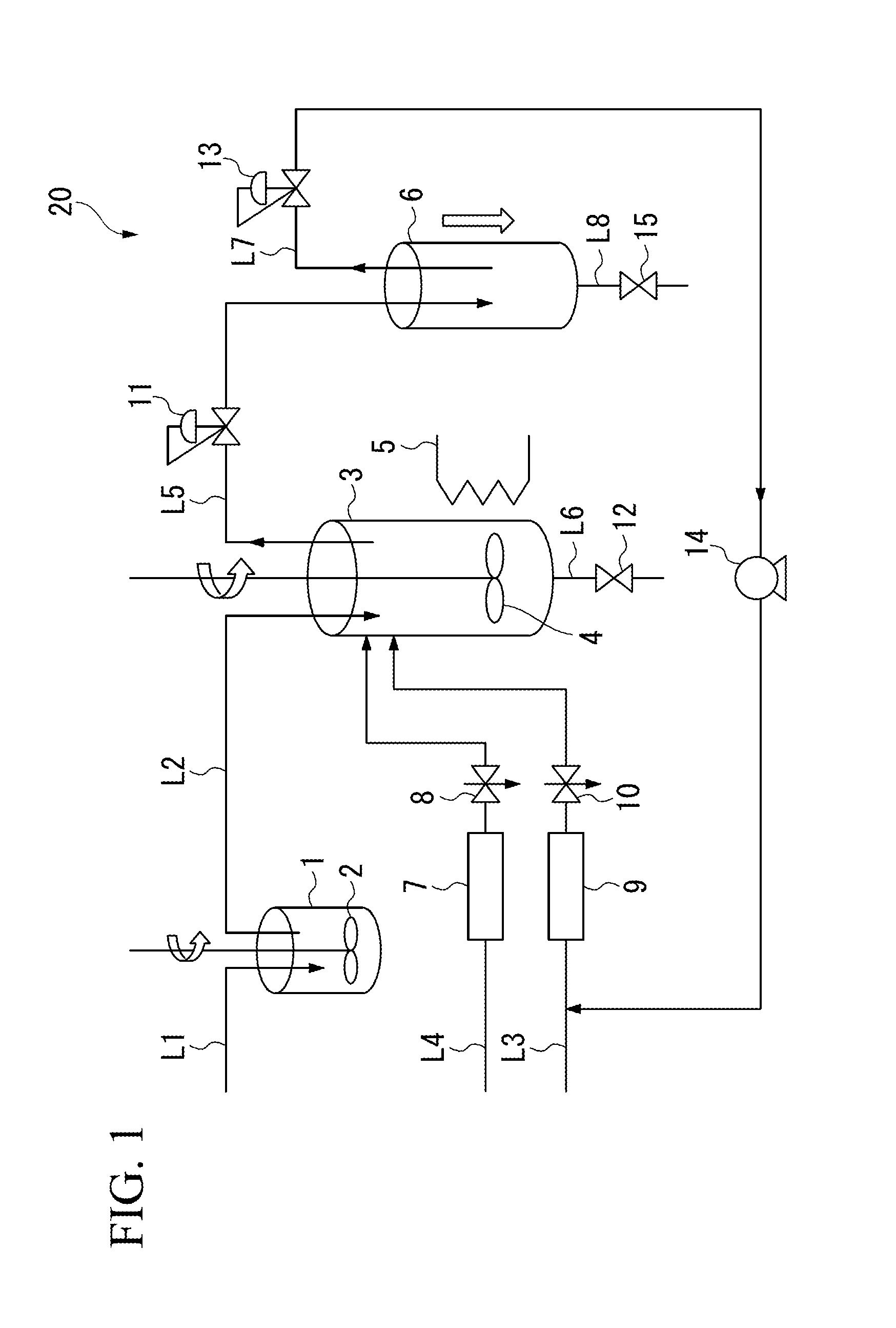
[0110]The apparatus shown in FIG. 1 were used to produce composite resin material particles by the procedures mentioned below.

[0111]First, a beaker was filled with 20 ml of ion-exchanged water, to which 200 mg of sodium cholate was added as a dispersing agent. Subsequently, the mixture was subjected to ultrasonic dispersion for 10 minutes using an ultrasonic disperser (ULTRA SONIC HOMOGENIZER UH-50, SMT Co., Ltd.; 50 W, 20 kHz), to prepare an aqueous dispersing agent solution.

[0112]Highly oriented carbon nanotubes (with an average diameter of 11 nm and an average length of 145 μm) were produced on a silicon substrate according to the method disclosed in Japanese Patent Application Publication No. 2007-222803, titled “CATALYST FOR GROWING CARBON NANOSTRUCTURE, METHOD FOR PRODUCING CARBON NANOSTRUCTURE, AND GAS AND CARRIER GAS FOR, AND APPARATUS FOR PRODUCING CARBON NANOSTRUCTURE”.

[0113]Then, the carbon nanotubes produced were detached f...

experiment 2

Relationship Between the Concentration of Carbon Nanotubes Added and Volume Resistivity

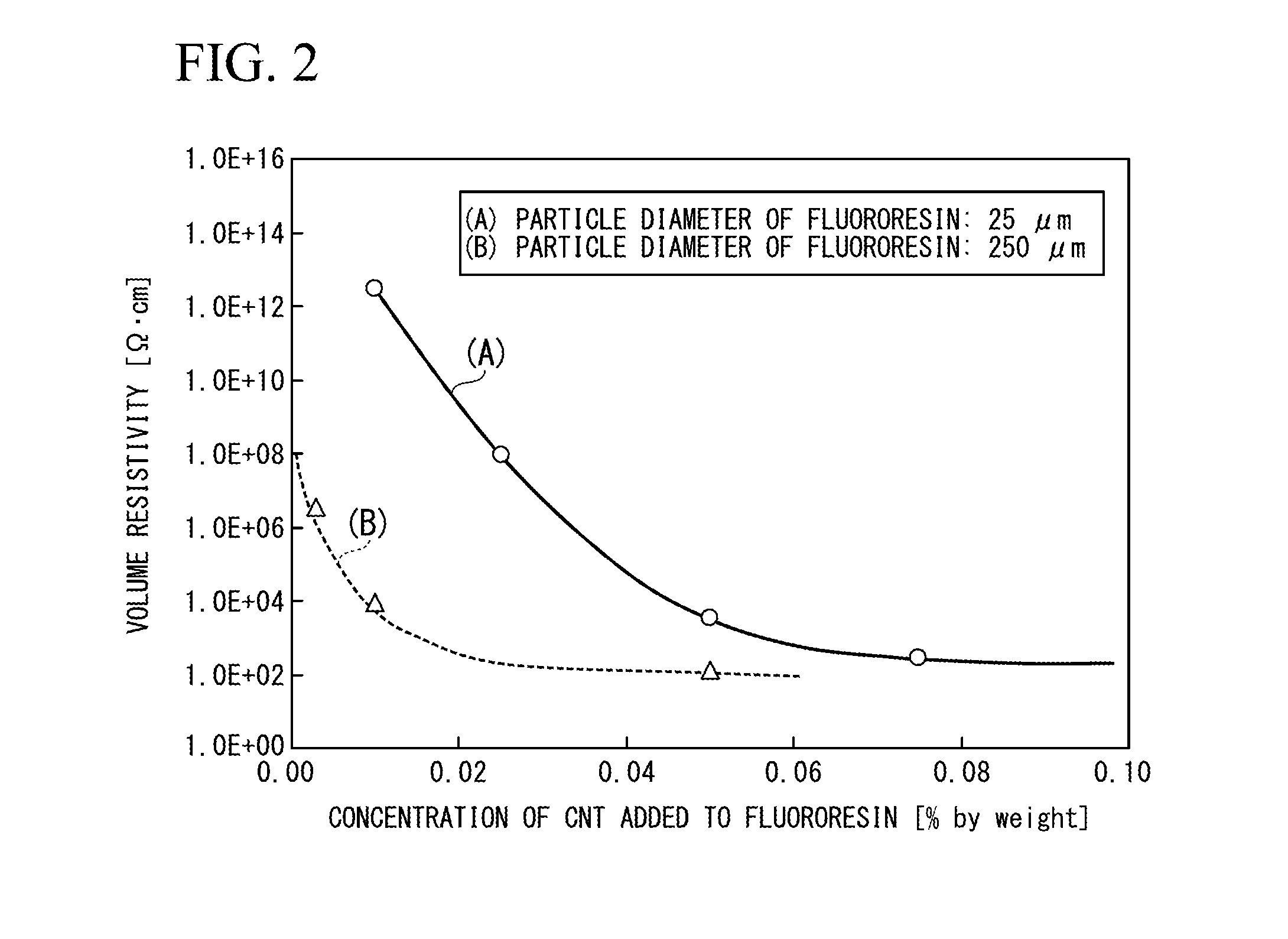
[0126]According to the procedures shown in the above-mentioned Experiment 1, electrically conductive fluororesin moldings were prepared in which the concentration of carbon nanotubes added was changed to 0.01%, 0.025%, 0.05%, and 0.075% by mass. Volume resistivities of the resulting electrically conductive fluororesin moldings were measured. The results are shown in FIG. 2. As shown by (A) in FIG. 2, these moldings had a volume resistivity of 2.81×10¹², 8.98×10⁷, 3.49×10³, and 268 Ω·cm, respectively.

experiment 3

Relationship Between the Concentration of Carbon Nanotube Added and Volume Resistivity

[0127]Experiments were carried out in the same way as the above-mentioned experiments where the average particle diameter was 25 μm, except that fluororesin particles with an average particle diameter of 250 μm were used as the fluororesin particles and the concentration of carbon nanotubes added was changed to 0.003%, 0.01%, and 0.05% by mass. The results are shown in FIG. 2. As shown by (B) in FIG. 2, these moldings had a volume resistivity of 3.45×10⁶, 8.90×10³, and 129 Ω·cm, respectively.


PUM

PropertyMeasurementUnit
lengthaaaaaaaaaa
lengthaaaaaaaaaa
volume resistivityaaaaaaaaaa

Abstract

A composite resin material particle is produced by a method including the steps of: forming a mixed slurry containing a resin material particle and carbon nanotubes; supplying the mixed slurry to a pressure vessel, followed by supplying carbon dioxide with stirring an inside of the pressure vessel; holding the inside of the pressure vessel at a temperature and at a pressure which allow the carbon dioxide to be maintained in a subcritical or supercritical state; and transferring the carbon dioxide to the outside of the pressure vessel.

Description

TECHNICAL FIELD[0001]The present invention relates to a composite resin material particle and a method for producing the same, a composite resin molding using such composite resin material particles, and a method for producing the same.BACKGROUND ART[0002]Carbon nanotubes are a tubular material in which a single- or multi-walled graphene sheet formed of carbon atoms is rolled into a cylinder. These carbon nanotubes have different properties, depending on the way the graphene sheet is rolled into a tube, and on the shape of the carbon nanotubes themselves, such as the diameter and crystallinity of the tube, and others, and are expected as a material that is highly attractive in characteristics of the material itself, such as electrical and mechanical properties, and specific gravity, in comparison with metallic materials.[0003]In order to make effective use of mechanical and electrical properties of carbon nanotubes in producing composite materials in combination with other materials...

Claims


Application Information

Patent Timeline
Patent Type & Authority Applications(United States)
IPC IPC(8): H01B1/12
CPCH01B1/12C08K7/24C08J3/12C08J2327/18C08J3/2053Y02P20/54C08L27/18C08K3/041
Inventor YAJIMA, TAKERUABE, TOSHIYUKISAKAI, TORUMIYOSHI, KENTARO
Owner NIPPON SANSO CORP
Why Eureka
Try Eureka