Particle tracking system and method

a particle and tracking technology, applied in the field of particle tracking, can solve the problems of pipeline systems that can have critical failures after being constructed, unreliable results for complex fluid flows, and significant time and effort currently involved in making crucial fluid system design decisions, so as to increase the amount of particle travel, increase the frame rate, and increase the effect of observable volumes

Inactive Publication Date: 2014-01-02
THE BOARD OF TRUSTEES OF THE UNIV OF ILLINOIS
View PDF4 Cites 79 Cited by
  • Summary
  • Abstract
  • Description
  • Claims
  • Application Information

AI Technical Summary

Benefits of technology

[0030]Preferred embodiment systems of the invention use a scalable number of cameras that can image a volume of interest from plurality of angles. The volume can be large and illuminated with general non-coherent illumination. Synchronized cameras process data in real time to addresses particle overlap issues while also increasing observable volumes. Systems of the invention also use higher frame rate cameras to increase the amount of particle travel in each frame. Approaches of the invention alleviate the concerns with additional data accumulation by conducting image processing and segmentation at the time of acquisition prior to transfer from a camera to eliminate a data transfer bottleneck between camera and computer and eliminate a data storage problem. A heterogeneous CPU / GPU processor cluster processes data sent from the plurality of programmable, synchronized cameras and conducting multi-camera correspondence, 3D reconstruction, tracking and result visualization in real time by spreading processing over multiple CPUs and GPUs. Systems of the invention be scaled to hundreds of cameras and fully characterize fluid flows extending to room size and larger.

Problems solved by technology

These models produce uncertain and unreliable results for complex fluid flows.
This often creates post-design testing and revision of prototypes and ultimately adds substantially to the time and effort currently involved in making crucial fluid system design decisions.
In addition, prototype testing with roughly approximated and unreliable fluid flow characterizations can produce pipeline systems that can have critical failures after being constructed.
Pipeline design and many other applications lack tools that permit non-invasive measurement of complex 3D flows, in real-world / full-scale environments.
These PIV and PTV systems were developed for researchers and experts, but have limitations when applied to practical analysis of natural phenomena and industrial applications.
The volume tested is limited both by the laser illumination and a desire to limit the amount of data acquired.
Acquiring information from larger volumes is viewed in the art as undesirable as the data then overwhelms the techniques used to characterize the volume that is acquired by the CCD cameras.
These PIV and PTV systems that are commercially available can only measure flow velocity fields because the systems base analysis upon two frames of data that are acquired in different points of time.
The resolution and accuracy of the particle tracking systems are naturally limited by hardware limitations from cameras, computers, illumination, etc.
Enormous data generation rates, low transfer rates, and finite camera memory combine to severely limit recording time to only a few seconds in most cases.
This limit leads to convergence issues in statistical analysis of Lagrangian motion.
Turbulent motion over the entire inertial range of eddies is of interest, but the small integration volume creates a constraint.
Solving the multi-camera correspondence problem in real-time for a large number of tracer particles remains a challenge that has not been addressed, except for the techniques discussed above that limit the number of cameras and the interrogation volumes.
Current commercial particle tracking velocimetry (PTV) systems, for example, are only capable of measuring flow field velocities, without particle trajectory reconstruction, in small scale flows (3) due to imaging and illumination system limitations.
Selecting the proper threshold value which maximizes the number of particle identifications in the presence of image noise, non-uniform illumination, and overlapping particle “blob” images can be difficult.
However, the present inventors do not know of the prior development of a single all-purpose algorithm that is optimal for all cases.
Despite this recognition, practical systems have failed to achieve this because of processing limitations and data bottlenecks.
Straw et al. described a tracking system that could trace the trajectory of several flies and trigger a secondary high speed camera based on a fly's location in real-time, but concluded that tracking hundreds or thousands of flies in real-time was outside the capability of the same or available algorithms.
Data accumulation has been recognized as a limit to achieving real time processing in particle tracking systems, but the typical approach is to store data with a large number of hard drives and conduct analysis of stored data.
The increasing frame rates and resolution of advancing camera technology impedes the ability efficiently to transfer, process and store the enormous amount of image data, and this problem has persisted with artisans having short observation time frames and / or small volumes.
A principal bottleneck occurs in data transfer between camera and computer.
This created convergence problems in their statistical analysis.
It has been effective to reduce the net data accumulation, but data still accumulates and when more than modest volumes are used, the data accumulation rate still places a significant constraint on particle tracking systems.
A drawback of this approach was that the system used one camera with a mirror system to split the image into four view points.
The single camera limits the effectiveness of the system.
Also, in these approaches and other prior approaches that speed the camera to computer transfer, a processing bottleneck alleviated at the camera is often shifted to the remaining required steps (solving the correspondence problem, 3D reconstruction, and tracking) to create a bottleneck at the computer used for processing.

Method used


Image

  • Particle tracking system and method
  • Particle tracking system and method
  • Particle tracking system and method

Examples


Embodiment Construction

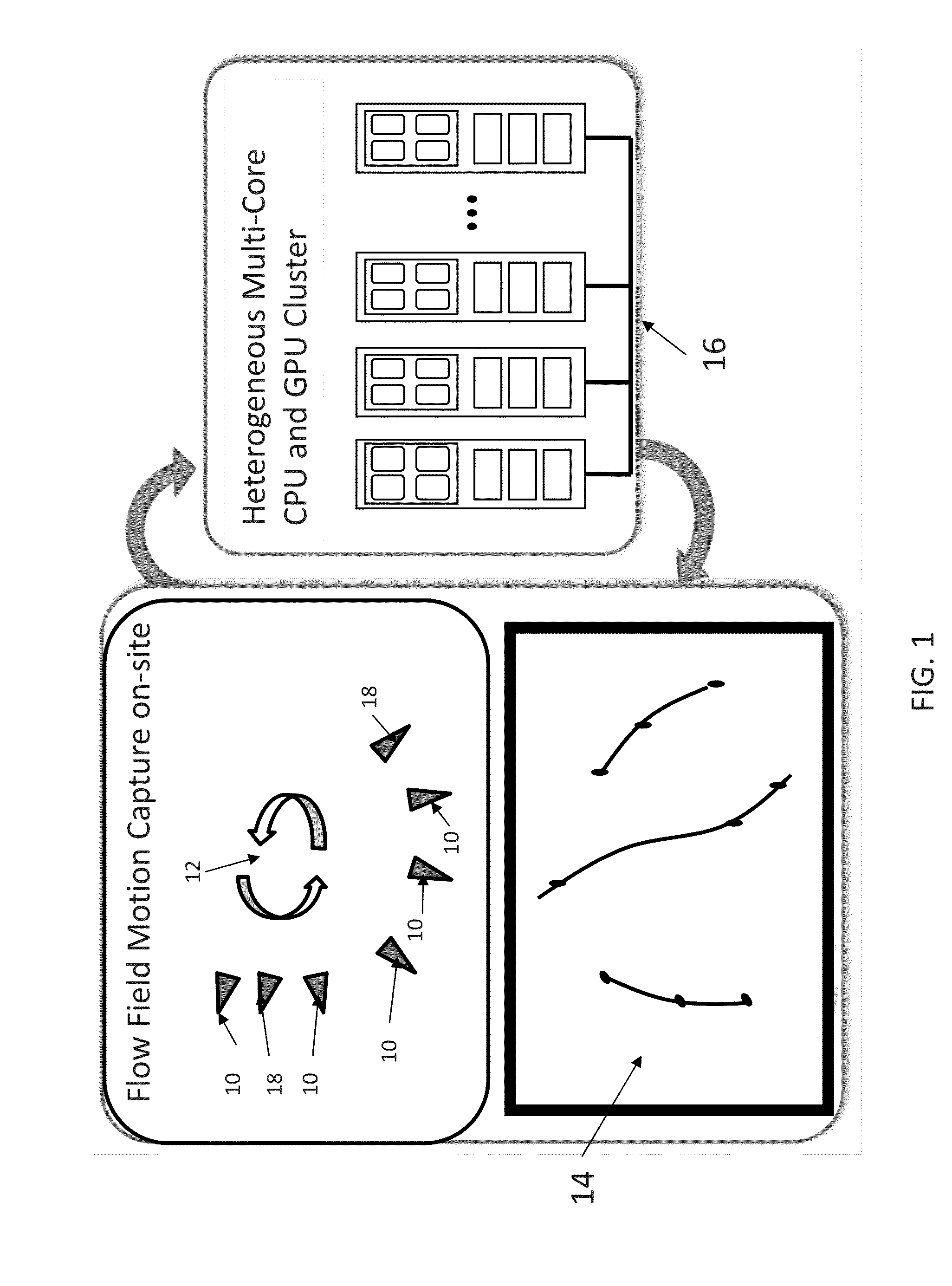
[0053]Previous approaches to particle tracking measurement systems try to develop and use complex algorithms in an effort to address hardware limitations to gain resolution, reduce errors and uncertainty, and improve usability. Preferred embodiments of the invention integrate a plurality of technologies and provide a scalable system to obtain more data than necessary and efficiently identify and analyze data that is critical while also identifying data that is unreliable and / or unnecessary (data that is a poor indicator of particle identification) and that can be discarded in real time to avoid what would otherwise be an unrealistic data storage problem. Preferred embodiments leverage parallel computing paradigms, heterogeneous computing architectures, smart cameras, and open source programming tools to overcome the particle tracking limitations and provide a solution that is scalable.

[0054]Preferred embodiment systems of the invention use a scalable number of cameras that can excee...


PUM


Abstract

Preferred embodiment systems of the invention use a scalable number of cameras that can image a volume of interest from plurality of angles. The volume can be large and illuminated with general non-coherent illumination. Synchronized cameras process data in real time to addresses particle overlap issues while also increasing observable volumes. Systems of the invention also use higher frame rate cameras to increase the amount of particle travel in each frame. Approaches of the invention alleviate the concerns with additional data accumulation by conducting image processing and segmentation at the time of acquisition prior to transfer from a camera to eliminate a data transfer bottleneck between camera and computer and eliminate a data storage problem. A heterogeneous CPU/GPU processor cluster processes data sent from the plurality of programmable, synchronized cameras and conducting multi-camera correspondence, 3D reconstruction, tracking and result visualization in real time by spreading processing over multiple CPUs and GPUs. Systems of the invention be scaled to hundreds of cameras and fully characterize fluid flows extending to room size and larger.

Description

PRIORITY CLAIM AND REFERENCE TO RELATED APPLICATION[0001]The application claims priority under 35 U.S.C. §119 from prior provisional application Ser. No. 61 / 664,788, which was filed Jun. 27, 2012 (incorporated by reference herein); and from prior provisional application Ser. No. 61 / 679,104, which was filed on Aug. 3, 2012 (incorporated by reference herein).FIELD[0002]A field of the invention is particle tracking. Example applications of the invention include systems for the analysis of particle dynamics in natural and industrial environments, including weather and environmental analysis systems and industrial control systems. Particular example industrial processes include industrial processes include aerosol separation in pollution control equipment (uniflow and reverse flow cyclones) and trapped vortex combustion in Integrated Gasification Combined Cycle (IGCC) plants.BACKGROUND[0003]The use of computational fluid dynamics (CFD) simulations is ubiquitous in research of natural phe...

Claims


Application Information

Patent Timeline
Patent Type & Authority Applications(United States)
IPC IPC(8): H04N13/02
CPCH04N13/0242G01N15/1463Y02E20/16Y02E20/18G06T2200/28G06T2207/30108G06T2207/30241G06T1/20G06T7/292H04N13/243
Inventor ZHANG, YUANHUIBARKER, DOUGLAS E.
Owner THE BOARD OF TRUSTEES OF THE UNIV OF ILLINOIS
Why Eureka
Try Eureka